electric bicycle as college project, couple of questions

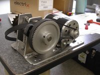
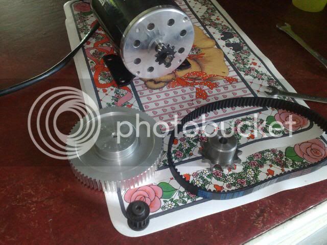
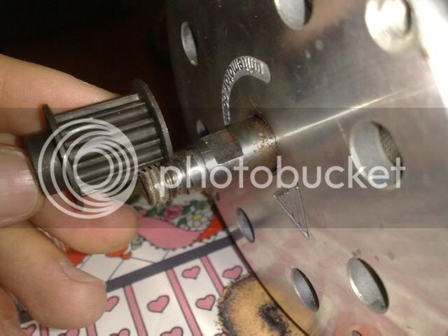
I'm pretty sure that scooter type motors come with sprocket for #25 chain which has 1/4 inch links. I have one of those motors but never tried to mesh a chain to it as a check. But I have a 90 tooth scooter sprocket that I scabbed onto the crank sprockets, and use #25 chain with it. It would be nice to have a rear wheel with dual drive, but crank drive is the most convenient place to run chain drive, otherwise. I have seen how members have scabbed #25 sprockets onto #40 bicycle chain ones. I keep forgetting if it is the #40 or the #43 that uses the 3/32" ten speed chain rather than the 1/8".

ES member research by Boostjuice seems to have found that the ACS Crossfire that has double supporting bearings should do well. http://endless-sphere.com/forums/viewtopic.php?f=28&t=25153&start=45#p386081

That buck/boost controller used a SMPS transformer that did double duty as the charger transformer. The transformer has its second job in push-pull drive at 12v, which doubles the voltage excursions to 24v. Then I ran the those 24v waveforms through a capacitor voltage doubler, which also acts as a current limiter by means of the capacitor's impedance. It was an extra layer of protection for stability and reliability since the feedback control is via current sense which offers the first line of protection. It also allowed the motor to be able to overvolt gently to reach that 40MPH with frantic pedaling.

Now since that idea, though technically a bit tricky, worked, i plan to try to build the next charger/controller with regular inductive buck/boost for the motor controller and then a small transformer for the charge circuit. Using a brushed motor enables that type of controller to be implemented much easier, or it might even be too hard to do with brushless in any remotely reasonable manner. I'm still contemplating that prospect as maybe an interesting idea to tinker with.
 
Right i've decided to go with the MY1020 1000 watt 48v motor for now just as a starting point and then possibly upgrade to an RC motor at a later date.
I am going to run a belt reduction system and then to a chain setup to drive a freewheel crank, but need some help on the reduction ratio to achieve 30mph top speed?
I was thinking possibly for the first stage around 3:1 using an HTD belt of 5mm pitch and 15mm width, and then possibly the same ratio again to the crank? The motors rpm is 3000 and the bicycle wheels are i think 26" mountain bike ones. I understand i need a crank rpm of around 100-120?

Any help would be greatly appreciated.

Evan.
 
Just (hopefully tomorrow, then wait for the machinist to finish my pulley) finishing up my build with a 5mm htd belt like you were thinking, will be running that at much more power, but you want the option to up the power at a later date anyway dont you? So I'm rigging the htd reduction first and going to a heavy duty #25 chain to a heavy duty white industries freewheel from sickbikeparts.com that is mounted on the cranks.

I machined the #25 sprocket to bolt onto the freewheel, with the chain cogs on the other side. Using a 55 tooth #25 cog, so if you were wanting to, a large reduction would be achievable here. I think my crank was for a little over 100rpm. Whiplash's build had around 120rpm I believe. A 15mm htd belt should be strong enough, and I hear they are very quiet, so it could be a great way.

Found a report of that motors running at 3600-700 rpm on 48 volt, so you would need a total reduction of 30-36:1, so a bit much for a 2 stage reduction, but should be possible with a 3 stage. But then again i may have been looking at the wrong motor, and it could be lower. I would ignore the top speed estimate and work on the crank rpm, get that to a good pedal speed (so 100-120) and the bikes gears should do the rest, long as you have a low enough speed option for climbing/startup.
 
Yeah i will be upping the power at a later date to achieve a better top speed and a little more torque. I have found a video on youtube showing a bicycle here in the UK using the My1020 motor connected straight from the motor to the crank via chain and sprockets and went fairly well, that why i was thinking to go a little bit reduced ratio to compensate for acceleration etc. I've attached a picture that shows the kind of setup i would like as this has a 3.8 1st stage reduction to a 22 tooth freewheel sprocket which i found on this forum (hope the member doesn't mind me using it).
So i'm really looking for around 30:1 to achieve around 100 rpm at the crank then?, does anyone know what top speed this would equate to?

Evan.
 

Attachments

  • my1020 reduction system.jpg
    my1020 reduction system.jpg
    81.2 KB · Views: 2,128
Funny coincidence, today I tested my 80-100 motor to dirt bike 1:5 gerbox to mongoose MB setup, then found your tread. My bicycle chain failed, have already mounted motorcycle chain and waiting for tomorrow test ride. Expecting over 80kmh. I am also waiting for new stock of 80-100s for other projects I have in mind.
Good luck!
 
parabellum said:
Funny coincidence, today I tested my 80-100 motor to dirt bike 1:5 gerbox to mongoose MB setup, then found your tread. My bicycle chain failed, have already mounted motorcycle chain and waiting for tomorrow test ride. Expecting over 80kmh. I am also waiting for new stock of 80-100s for other projects I have in mind.
Good luck!

That should be good then with 50mph+ top speed. I didn't make the above motor reduction system pictured as i found it on here and wondered if i could do something similar. Have you got the right topic?

Evan.
 
Sorry, I do not have any topic of this, but I can make some pictures and share end results of test ride. It is very simple, cheep materials home made setup. As stated before (from other members), the chain in the gearbox will be the weakest link, but there are reinforced boxes with double chain (sprockets are double to), I have not seen one on sale, but I know that member “olaf-lampe” has one, you may ask him if you have interest of doing it this way. There is also cheep 30U$ 7s 190Amp esc from hobby king used.
http://www.hobbyking.com/hobbyking/store/uh_viewItem.asp?idProduct=14500
 

Attachments

  • Picture 004.jpg
    Picture 004.jpg
    191.4 KB · Views: 2,814
Does it work? we need videos!
 
That looks great, how is the motor connected inside to the clutch housing part? I don't suppose you have used the dirt bike/mini moto centrifugal clutch attached to the motors shaft? I thought those gearboxes have cogs inside as i've taken them apart before, unless i'm mistaken, maybe i could use a box like this on my MY1020 motor as a sort of reduction system.
Would be great to know how your test ride went.

Evan.
 
Whiplash said:
Does it work? we need videos!
Sorry, it did not work. Motorcycle chain is cool but I just fried controller accelerating at about 40kmh 6s Lipo 2900Wp. So no Videos about Fiasco.
I also have Aquastar Monster ESC on my scooter but it is water cooled and it is a kind of PITA dis and assemble everything, I will probably first try to fry 3 more of cheep ESCs. :D

bike_electric said:
That looks great, how is the motor connected inside to the clutch housing part? I don't suppose you have used the dirt bike/mini moto centrifugal clutch attached to the motors shaft? I thought those gearboxes have cogs inside as i've taken them apart before, unless i'm mistaken, maybe i could use a box like this on my MY1020 motor as a sort of reduction system.
Would be great to know how your test ride went.

Evan.
The motor is to slow to use centrifugal clutch, it is “hard coupled”. It means, I fixed 3 pins inside clutch bell and the centrifugal inner side fixed on the shaft is pushing against them (I will need to fabricate some rubber or silicon damper in between later, to avoid metal rubbing against metal). Yes to run it from sensor less esc I need to be in motion already.
There are some gears with cogs, but they are les durable (in my opinion, due to small contact area), my works sprocket-chain-sprocket. (chain is that funny mini bike standard).
Just write, if you need some details and or photos,
 
Pareabellum: thats a shame to hear that, hope you get it sorted soon.

I've decided to go for a 12 toothed pully to a 72 tooth for the reduction (from motor) then from this i will run a 12 tooth sprocket down to a 48 tooth freewheel crank assembly. This should give me an overall reduction of 24:1, so this means the motor is spinning at 3000rpm/24. This equalls 125 rpm at the crank so this sounds pretty good to me. Now just to get building it, i've already got my motors controller and twist grip hall effect throttle, just waiting on the motor now which should be here this week. Ordering the pulleys etc this week aswell. Does anyone know if drilling a hole through a jackshaft and pulleys will be suitable to hold them on (so basically a roll pin) with a bolt or similar. Unless you can by a metal rod with a sort of keyway in it to allow a grub screw to tighten onto?

Evan.
 
I think your approach is better then my. But why are you reducing so far down? You reduce 24:1 for after go up from 1:4? Because if your wheel is 26” you will need about 500rpm on your wheel for 40mph. It only makes sense if you have in mind to put higher(>12k) rpm motor later? It is not good unnecessarily to multiply friction surface.

Or I am badly misunderstanding something and you will just assist your pedal setup? :?:
 
The reason for choosing the 24:1 reduction ratio to the crank is so that i can get a crank rpm of around 125, usually people on here are trying to achieve a crank rpm in the region of 80-120rpm. I am intending on using the unite MY1020 motor for a while and then when funds allow go for an RC setup. I still have the ability for using the rear wheel gearing cassette to allow hill climbing etc so i thought this would be ok? The motor to jackshaft is a 6:1 ratio and then the jackshaft to crank will allow a further 4:1 reduction. Multiply these together and it will give an overal reduction of 24:1 if this is what you wanted to know about?

Evan.
 
No worries, yeah crank part with the pedals, thought i was doing something wrong for a minute, as it took me a while to figure out the crank rpm calculations :D
Will post up some pics when i've got the reduction system constructed and the parts arrive.
Evan.
 
reduction sounds do-able, but one problem I ran into with bike chain (not sure what you are using) to the cranks is that the larger gears mean it must be offset further for my bikes geometry, the offset will make the chain need to move diagonally to the rear cluster too much, so I could not use half the cassette.

By going to #25 chain I could reduce the size of this gear significantly (1/2 the size) meaning I could have the crank offset only slightly from stock, and I could use an extended bb spindle rather than one I had to Frankenstein and weld myself, so it wasn't heat treated or anything. Waiting on this spindle and a pulley to arrive before I can run it though.
 
Thanks for the heads up. I'll be using a bicycle chain as the sprockets on the freewheel crank are the 1/2" pitch which i think bicycle chains are? When i get it all assembled i will see whats what and go from there if anything needs altering.

Evan.
 
I've got my belt with pulleys and a bicycle pitched sprocket to mount to the jackshaft but have come to a problem. The problem is that the smallest pulley which attaches to the motor will not be able to fit to the motors shaft properly. This is because there is only a small amount of thread from the original motor sprocket and if a thread is put onto the pulley then it will not have enough engagement to secure it properly. I've attached pictures of the problem and was wondering if the other shoulder part with the flats on it could possibly be threaded to take the pulley on a little further. I know the pulley is very small and this limits the size of the hole allowed in the pulley, so thats why i was thinking of threading it onto the motors shaft if this makes sense.
Any ideas would be very much appreciated. Thanks, Evan.

bicycle.jpg


bicyclemotorandpulleys.jpg


bicyclemotorshaftwithsmallpulley.jpg
 
yup, this is exactly what I did for my T5 pulley.

There will be a little slop in the shaft that lets it pull in and out of the motor, only a mm or less, so not much. If you push the shaft in, and mark about 1mm or so from the bearing you will be sure to still have full contact with the bearing after you cut the shaft down. As long as you make sure the shaft stays thick where it contacts the bearings, the thread is not too small and the pulley does not run on the motor can, then you will be fine.

With mine I cut the shaft down from 10mm to fit a m8x1 thread (make sure you take the shaft out completely before you fit it in the lathe), chucked the pulley in the lathe as well and drilled a hole in the centre, then tapped this to the same thread. End result was the shaft with a smaller threaded rod out one end. For my current (htd) pulley it had a half moon already cut into the pulley stock, so I cut a flat spot on the shaft to fit.

Just keep in mind that the shaft can unscrew the pulley when you go, so you want to tap it in the direction that will screw the pulley onto the shaft when the motor is running. Mine used regular thread, but depending on your setup you may need to use reverse thread taps (yes, you can get them). You don't need to worry about this part if its cut to a half moon though.
 
Thanks for the help Bandaro, so what i'll do is take the complete shaft out of the motor and then have both of the steps machined down to accept an 8mm or so thread (same as the original thread but just longer) to hold the pulley on properly. Failing this, i thought i could machine out one end of the pulley to fit over the larger stepped parts in the motors shaft and then thread the pulley roughly 3/4 the way inside therefore sliding on further and still using the stock threaded part? The stepped parts beyond the original thread seem to be 10mm with 2 flats on it (to hold on stock sprocket) and then around a 12mm shaft with another 2 flats (to hold shaft with spanner etc when tightening the nut for the stock sprocket).

Also as i can't buy freewheel adapters here for the likes of bmx freewheel rear sprockets i was thinking of using the hub off a shimano cassette, remove the cassette and then cut down the hub to leave the freewheel threaded part. Only trouble is i think it's a righthanded thread when it needs to be left handed for the bmx freewheel? Has anyone tried this before?

Evan.
 
Not sure i"m following, but I'll try..

So you mean that you need the threaded part of the wheel hub that a cassette screws on to?

What do you want to use it for? If it is the threaded part of the rear wheel, that the cassette screws onto then you can use one of the bearing cup holders from the bb, you know the parts you unscrew to get the crank axle off that wedge the bearings between the axle and them self? From memory is it the left hand side that screws straight into a freewheel.
 
Yeah i mean the threaded part which the cassette screws onto on say a mountain bike. What i was going to use it for is to secure a freewheel onto the motors reduction systems jackshaft by building/constructing a part to weld or secure on somehow to the freewheel adapter using the side where the spokes fit on a normal bicycle. So the hub will be cut down the where the spokes fit if this makes sense and then a bmx freewheel screwed onto the adapter? I have found a website which will explain better the part i mean in figure 10 etc. I'm not too sure on the method you were suggesting using the bearing cups etc.
It is the left hand part which screws into the cassette on the bike if it's on the bike as it is with all bicycles and bmx's i think as shown on website.

http://www.atomiczombie.com/ct-freewheel.html

Evan.
 
yup, thought so.

So yeah, get an old broken bike, from the rubbish dump or some place. Then unscrew the bottom bracket bearing holders and they will screw straight into the freewheel assembly, promise.

You will have to buff it down first though, you wont be able to weld onto it properly unless you take the coating off it before hand. And by buff I mean with a disk sander/wire brush on an angle grinder. This is exactly what I had to do for my gearbox, 17mm shaft with a bb holder welded on, be sure to lathe down a thick enough bar to leave a fat spot to push the bb cup onto to make sure it will be sitting straight. Otherwise you can get the chains jumping or wanting to jump off, then you cant run until you take it apart and put them back on...
 
Thanks for the info. Just out of interest do you have any pictures of your assembly. I'm not sure if a bmx freewheel will screw onto the cassette type freewheel adaptor hub part as the cassette screws on clockwise whereas bmx freewheels are left handed threads, so would this mean i need a bmx hub rather than a mountain bike one with the cassette?

Evan.
 
wait, what? how can they screw in different if they are both driven on the same side... if the thread was the wrong way then they would just unscrew when the chain started to twist the freewheel, so they can only be the one way.

I have not tried a geared cassette, admittedly, but it screwed into the freewheel I got for a bmx, and it screwed into the white industries one I got for the cranks. No pictures of the setup as its in a sealed gearbox, and as the batteries are only taped in yet to make fibreglass box it is a pain to take it apart.

Gimme one sec and ill buzz outside and check on a cassette...

Edit: yup, I was right, screwed straight into a geared cassette from a mountain bike as well. So left hand bb bearing cup holder fits any screw in freewheel.
 
Back
Top