• Hello ES! We could use some help to get us past the finish line on building the new knowledgebase for the forum.
    Can you donate? Please see our fundraising page. Thank you!

Electric Cart Build

4TKR

New here
Joined
Jul 21, 2025
Messages
8
Location
Queensland
I have built an electric cart for my wife to get around our small acreage as she is not very mobile. I am hopeless at electrics and need some help in wiring it up.
It has a 24v 500W motor, ignition switch, twist throttle and forward/reverse switch. these run through a 24V 500W controller and 2 x 12 v batteries wired to 24V.

I can get it to run with just the twist throttle and ignition switch but as soon as I wire in the FR switch the wiring starts melting and the controller burns out.
I have found another controller with just a FR switch and wiring to the batteries and motor.
Can I run 2 controllers - one for FR switch and the other for the ignition switch, twist throttle and battery charger?
If so, how do I wire it up and do I need relays in the system?

Thank you
Frustrated...
 
Hello, what kind of motors and controller are you using ?

if you have BLDC with hall sensors (like e-scooter, e-bike or hoverboard motors, with 3 thick wires and 5 thin wires), and a controller without Fwd/Rev wires, you need to have a relay to exchange 2 of the 3 thick wires and also a relay to flip 3 of the 5 thin wires
if you have a sensorless BLDC motor (without the thin wires), you need a relay to flip 2 of the 3 thick wires connected to the F/R switch
if you have a brushed DC motor, you need just a relay to flip the 2 thick wires
these are valable if the controller don't have a true F/W plugs

the best solution would be to find a controller with a true F/W input plug, and a motor optimized for both directions
 
I have built an electric cart for my wife to get around our small acreage as she is not very mobile. I am hopeless at electrics and need some help in wiring it up.
It has a 24v 500W motor, ignition switch, twist throttle and forward/reverse switch. these run through a 24V 500W controller and 2 x 12 v batteries wired to 24V.

I can get it to run with just the twist throttle and ignition switch but as soon as I wire in the FR switch the wiring starts melting and the controller burns out.

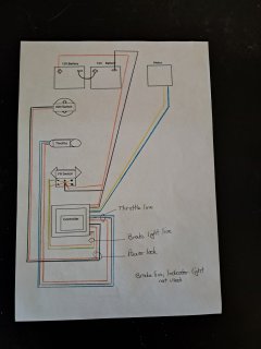
Can you create a drawing of *exactly* how you have it wired when the problem happens? Not how you think it might be wired, but actually tracing out every wire, connected or not, and draw where exactly they go, and what each wire is for on each device that is connected, everywhere on the vehicle.

This will help us help you find out which thing is wired wrong.

Another thing that will be needed is the specifics on each part you are using. Links to the specific page for each item on the website they were purchased from will also help, if available. Otherwise, exact model numbers and brand names so we can look up their manuals for wiring and function and voltage/etc limits.


I have found another controller with just a FR switch and wiring to the batteries and motor.
Can I run 2 controllers - one for FR switch and the other for the ignition switch, twist throttle and battery charger?
If so, how do I wire it up and do I need relays in the system?
I don't understand what you want to do.

A battery charger is not part of, nor involved with, any controller. It is a separate item that only connects to the batteries' charge port. If they don't have separate charge ports, then it connects to the same main + and - as the controller does. So you don't need a controller for it.

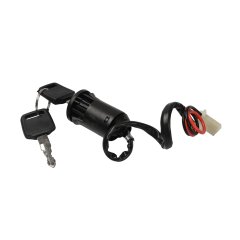
An "ignition" switch is used on every controller (normally) to turn it on or off, so that it is only able to drive the motor when you have enabled it to do so, and cannot unexpectedly operate it from an inadvertent user input. So you wouldn't have one controller with one, and one without one.

A forward / reverse switch would only be used on a single controller to operate a motor in two possible directions. You would not use one on just one controller and not on the other, if both controllers are intended to drive the same motor.

If you require two separate controllers for some reason, one to drive the mtoor forward, and the other reverse, you would just permanently wire the one controller in forward, and the other in reverse. There are different ways of doing that for different types of motors and controllers, but we don't know anything about which kind you have, so I can't offer any specific advice.
 

Attachments

  • controller labelled.docx
    919.1 KB · Views: 5
  • Forum Wiring.jpg
    Forum Wiring.jpg
    986.9 KB · Views: 10
  • FR 6 pin.docx
    163.1 KB · Views: 1
  • Giantz battery.docx
    97.4 KB · Views: 0
  • Ign switch 2 wire.jpg
    Ign switch 2 wire.jpg
    101.4 KB · Views: 9
  • Motor label .docx
    106.8 KB · Views: 0
  • Twist throttle wires.docx
    187.5 KB · Views: 1
Last edited:
Ok, so, this is a brushed (two wire) motor system, so it's possible to do reverse in a couple of ways.

In your case, the F/R switch isn't on the controller, switching the controller itself to a reverse mode (so it doesnt' matter if the controller supports reverse or not). It's actually swapping which wire from the motor goes to the controller. That means it's (hopefully) a large hefty switch that can handle all the current the motor would ever draw even under worst case conditons...

These switches always get wired between the motor and controlelr, only. Never to the battery, and never to the brake light.

Your diagram shows battery power going to the center (common), and the output of the switch (the two ends) wired to the controllers' brake light output. That brake light output on the controller would normally have to connect to a relay that then connects a separate 12v (or whatever) battery to your brake light, whenever you pull the brake lever that's wired to the controller. (controllers usually can't output enough current to drive a light from these pins, and can be damaged by trying).


The way the FR switch *should* get wired (colors taken from your drawing):
The common (center) pins each get one of the controller's motor output wires, doesnt' matter which one on each, as long as they are separate. So blue to one, yellow to the other.
The two end pins on one side will then be wired to the motor itself, doesnt' matter which one on each. So blue to one, yellow to the other.
The two end pins on the *other* side will then be wired to the motor itself, but swapped. So yellow to one, blue to the other.
Then when you have the swtich in the center position, it's off. Forward is one way, and reverse is the other. If it matters whcih one is which, then the simpel way is to wire it and test it, and if ti goes opposite, swap the motor wires *at the motor*.


For your wiring diagram, for yourself for later troubleshooting, and for making a diagram that lets you correclty wire stuff up before turning it on, I highly recommend you label each individual wire for what it is. For instance, the throttle input has a power wire, a ground wire, and a signal wire. Color of wires is not standardized, so you can't really depend on that always matching. If the information that came with each part doesn't tell you which wire is which, perhaps the seller can tell you. Otherwise you ahve to determine experimentally, and that can let smoke out of things. :(
 
Wow! Thank you very much. I'll now let that sink in and try to do it.

I really appreciate your input.
 
Well in spite of the great information I've been given I am getting nothing but trouble - melting wires etc. If I forgo the forward reverse switch (that's when the trouble really starts) and just wire the motor, power switch, battery and throttle through the controller I can get it to work. Unfortunately I stuffed the controller so I bought a new one the same. The new controller gets power from the batteries ok, the motor gets power from the controller ok, the on/off (power) switch also works ok. It seems like there is no signal from the controller to the throttle - I have used a test light on both sides of the connectors from the controller and there's nothing. Obviously I've done something wrong again...
 
Which kind of throttle is it?

There are potentiometer types, and hall types. Each has a different voltage range. P=0-5v, H=~1v-~4v

Some controllers that require a pot type can't work with a hall type because of their electronics design; a safety feature in case a throttle wire gets disconnected.

Some work with them *but* beause the hall starts at a nonzero voltage, the controlle rpowers on and sees a voltage and anohter different safety feature prevents operation because it sees what is called "pedal high at startup" on some types, as if you had the acclerator already pushed down and in gear when starting a car you wouldn't want it to vroom off. ;)

So...need to know which throttle type you've got, and which type the controller requires, to eliminate those issues.

Also, if it's a hall type, it could be fried by the miswire of the reversing relay that fried other things inside the controller. You can test it with a voltmeter, with it connected to the controller and everyting powered up, it should vary in voltage on the signal wire as you turn it.

A pot would probably not be damaged, but you can verify it with the ohm reading on a multimeter, with the throttle disconnected from everyting else.
 
I only know that the throttle and controller were supposed to be compatible when I bought them from the same place. It did work before I fried the wires which have been replaced. There is no power/signal coming out of the controller.I tested both sides of the connection with one of those circuit tester lights.
 
Which specific "circuit tester light" are you referring to? If it is not made for the signals / voltages that this system is using, it probably won't provide you valid / useful test results.

A voltmeter / ohmmeter / multimeter is probably going to be required to figure out what is going on.


If there is "no power" coming out of the controller, which specific wires are you testing at?

Which specific controller wires are connected to which speicific battery and motor and throttle wires? I recommend tracing out every wire as they are actually connected, right now, drawing them out on paper, labelling them as you do it, for which wire they say they are on each part of the system.

If they are all correctly connected as needed, and nothing extra is connnected, and nothing required is disconnected, then it may mean the controller is defective or damaged.

It might also be that the throttle itself is damaged in a way that causes the controller's power to it to be dragged down to the point the tester you have can't detect it.

Need more data to eliminate possibilities.
 
With the help I've been given, plus some trial and error, I've just about finished the cart. If I wanted to run another 24v 500 w motor would I need more batteries or are the 2 x 12v ones connected as 24v I'm using be enough or would I have to get more batteries. Also would it just be a matter of piggy backing the motor wiring into the 24v 500w controller I am using? My thinking is (whether it's right , wrong or just plain stupid :) ) is that it might give the cart just a little more power and easier to go from still to moving.
 
Back
Top