You are using an out of date browser. It may not display this or other websites correctly.
You should upgrade or use an alternative browser.
You should upgrade or use an alternative browser.
Electric Roadster
- Thread starter Dui ni shuo de dui
- Start date
Dui ni shuo de dui
100 kW
darkmunk said:Love this build.
Well done!
Can't wait to see the finished product.
Thanks darkmunk, much appreciated!
I can't wait to have it finished either, but it's coming along pretty well so far.
Some progress over the past week:
I worked on a stand for the bike. The original one was really too low so that would have been an issue while cornering, plus it was insanely heavy for it's size, weighting a whopping 1 kg. That might sound like not a lot, but it's really heavy for such a small thing. Anyway, I built a new one using some scrap of carbon fiber tube I still had from he other stuff I made.
I had to add a small bracket to attach the stand somehow to the bike. I tried several things, but the one which worked the best was to put the bracket on the swing arm. I know it's a bit weird, but it was the best way to keep the stand short and to keep it away from rubbing the road in any circumstance. Since it is extremely lightweight I'm not worried at all about unsprung mass and whatnot, I removed much more weight on the swingarm so far than I added with this thing:
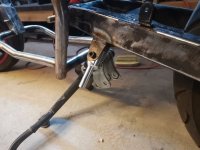
The aluminum parts were turned on my mini lathe and I 3D printed a removable cap to act as a sacrificial contact point to the floor.
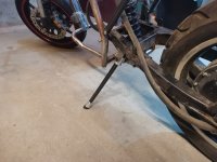
The new stand weights only 180 grams. It works very well, but I'll need to make a small system to adjust the stopping position as well as to work on some kind of spring. Will do that later.
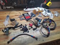
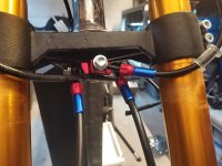
Next, I ordered and received all the necessary things for the brakes: new fittings, new brake pumps, new lines... Unfortunately the brake pumps weren't as nice as expected so I'll return them and get better ones, but I do really like the brake lines who mimics a bit the fuel lines of airplanes or high performance cars:
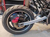
Last but not least, I started to prep the swingarm. I cut away all the unecessary brackets, took a long time with the grinder to sand down to bare metal, smoothed the welds, then used putty to make it look a bit cleaner and finally gave it a nice coat of primer.
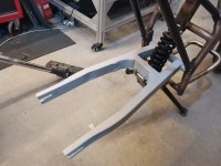
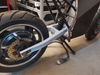
The goal here is just to protect it from rust because I don't know how long it will take to finish all the other things. So in the end I plan to sand it one more time, then another coat of primer and finally the first coats of paint. I might have to weld some additional brackets later also. I'll do the same for the rest of the frame too.
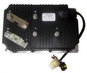
Also, I got a good deal on a second hand controller, so now I know what will power up this thing: it will be a Kelly KLS72701 ( https://www.kellycontrollers.eu/kls72701-8080i ), with a maximum of 700Amps per phase and something like 500 battery amps peak.
I hope that the motor will be able to take all that power without releasing any smoke, guess we'll see. One thing for sure: that will be a really powerful beast, the ratio torque/weight will be pretty crazy, can't wait to try that!
Attachments
JimVonBaden
100 W
This is an outstanding build. Your attention to detail and skill are very very good! I will definitely want to see how this progresses.
By the way, gel seats are very comfortable, but beware exposing them to the sun, they will burn your balls, even through your jeans!
Jim 8)
By the way, gel seats are very comfortable, but beware exposing them to the sun, they will burn your balls, even through your jeans!
Jim 8)
SlowCo
1 MW
darkmunk said:Hope you have a hefty torque arm for the motor
You're kidding, right? There is a torque plate and the whole steel swing arm is a torque arm :wink:
Dui ni shuo de dui
100 kW
darkmunk said:Hope you have a hefty torque arm for the motor
SlowCo said:You're kidding, right? There is a torque plate and the whole steel swing arm is a torque arm :wink:
Actually that's a valid question: currently I'm only using the original QS torque plates, which, from my experience, aren't always up to the task when it comes to really high torque figures, especially when frequently changing from high acceleration to regen braking. Tends to grind these plates as well as the axle slowly over time.
I was not planning for using such a powerful controller in the first place, so I haven't really thought of beefing up the motor attachment points. It's actually a good thing that darkmunk pointed that out because I might have missed it otherwise :wink:
What we've done with a friend on his high power motorbike was to design a torque arm that would clamp the motor shaft very firmly in place, out of some very thick 7075 T5 aluminum. I might reuse this design if it turn out that the motor is moving, I will keep monitoring the motor position regularly during the first weeks/months of use and see if it's necessary for this amount of power. Thanks for bringing it up!
That's hat I like about posting my builds in the forums, you always get some interesting inputs from nice folks willing to help!
SlowCo
1 MW
I agree that, when using regenerative braking, a clamping torque plate or arm is a better solution.
But that doesn't mean that the plate you are currently using that came with the motor is not strong enough. Just that the little play between the hole in the plate and the shape of the axle will cause wear and damage over time due to the counter active forces. So it's indeed a good idea to make a thicker (more surface) and clamping plate to save your axle.
But that doesn't mean that the plate you are currently using that came with the motor is not strong enough. Just that the little play between the hole in the plate and the shape of the axle will cause wear and damage over time due to the counter active forces. So it's indeed a good idea to make a thicker (more surface) and clamping plate to save your axle.
mannydantyla
100 W
- Joined
- Dec 4, 2020
- Messages
- 127
Really cool build and amazing rate of progress! I'm impressed
If you're worried about the controller providing too much power for the motor, maybe you could try applying some "statorade" to the hub motor - https://ebikes.ca/product-info/grin-products/statorade.html - they claim "you can run it at roughly 40% higher sustained torque and power without overheating."
What kind of range are you expecting/hoping to get with 40ah?
Nice build!
About that 3d printer. You must be using a 1mm nozzle. What was your layer thickness on the cover? I’m envious as I’d love to print an entire bike wheel, need 600 x 600 min. Have you considered the wax filament for the sand casting that you want to do?
About that 3d printer. You must be using a 1mm nozzle. What was your layer thickness on the cover? I’m envious as I’d love to print an entire bike wheel, need 600 x 600 min. Have you considered the wax filament for the sand casting that you want to do?
Dui ni shuo de dui
100 kW
mannydantyla said:Really cool build and amazing rate of progress! I'm impressed
If you're worried about the controller providing too much power for the motor, maybe you could try applying some "statorade" to the hub motor - https://ebikes.ca/product-info/grin-products/statorade.html - they claim "you can run it at roughly 40% higher sustained torque and power without overheating."
What kind of range are you expecting/hoping to get with 40ah?
Thanks manny!
I might give statorade a shot, but I'm not sure if I can find this in China. Also I try to avoid opening my motors when it is not absolutely necessary, because I don't want to mess up the factory alignments. But I'll give it a second thought if it turns out that the motor heats too much.
As far as range goes, I don't really care. My objective is to be able to do at least 26 kilometers per day, since this is the distance of a round trip from my home to my office. I know for sure I will be able to do much more than that, so that's not a problem. Range is totally dependant on the riding style, so I expect to have something between 40kilometers if driving like a maniac, up to 100+ kilometers if driving real slow. The main characteristics I'm looking for on this battery are current delivery capability, long term reliability and general safety/convenience to use.
Dui ni shuo de dui
100 kW
Skaiwerd said:Nice build!
About that 3d printer. You must be using a 1mm nozzle. What was your layer thickness on the cover? I’m envious as I’d love to print an entire bike wheel, need 600 x 600 min. Have you considered the wax filament for the sand casting that you want to do?
Thanks Skaiwerd!
On this printer I'm currently using a 0.8mm nozzle and a layer height of 0.4mm.
I haven't tried the wax filaments yet, that's a good suggestion actually I might give this a shot. I already did lost PLA casting, it worked ok but it stinked up the place while the PLA was burning, that was not a very pleasant experience. So yeah, I'll try to find some, thanks for the suggestion!
Just note that, at least as far as I know, wax doesn't work well for sand casting, but it does work well for plaster/investment casting :wink:
Dui ni shuo de dui
100 kW
Some new updates:
I received almost all the necessary hardware to get the bike running, yay!
New handles:
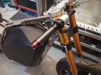
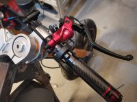
New brake pumps:
(these are "chinese versions" of brembos, so that was dirt cheap, but they do feel like really nice quality, it was a good find)
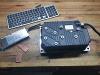
And, last but not least.... The massive Kelly KLS72701 Controller!
This controller features variable regen. I'd like to try using it, but I'd like to limit it to a relatively low level in order not to mess up the battery too much. Also, I'd like to keep the hydraulic brake for obvious reasons.... But Ideally, I'd like to operate both of these with one single lever.
So I had this weird idea I'm gonna test: using a clutch actuator to command a cable throttle. I'll parallel the rear brake system to this little actuator. The idea is that whenever I press the lever, brake fluid will first push the actuator since there's very little resistance there, moving the potentiometer until it reaches the full stroke of the actuator. Then once the actuator is maxed out, pressure should increase more and more until the brake pads press the disk.
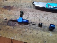
In theory this should work, but I'll have to reduce the internal volume of the brake pump cylinder in order to use less lever travel to max out the potentiometer.
Anyway, I'll try that, hopefully that will work.
Also working on a sytem to better enclose and connect my ANT BMS. This BMS is really nice, but the main flaws are that it doesn't come with an enclosure, and also you have to solder the power wires directly on it, which I find extremely unconvenient.
So I bought a 100x100mmx4mm pure copper plate, and used my trusty hack saw + file to create those two bus bars.
They will be soldered to the BMS terminals, and then I could just use a screw to secure the power wires to it.
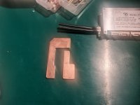
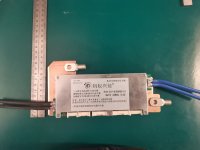
I'm in the process of designing a 3D printable enclosure for it, hopefully it should be nice.
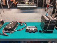
Now that I received the controller, I can finally check how to actually fit all this hardware into the bike. So far, I'm leaning towards this configuration, which is very compact and gives the lowest possible center of gravity, while making everything super accessible and using very short power wires. No real downside aside that it will make cooling the controller a little bit more complicated, but that something I can easily fix with an air scoop on the bottom of the bike, or even later with water cooling if it turns out to be necessary (but it won't).
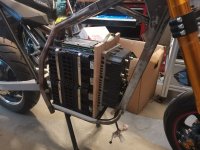
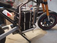
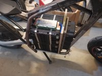
Now I need to replace this cutting board wih a metal bracket, probably some CNCed aluminum. The battery will be secured in place by pressing it from the top using a metal plate. I'm thinking of using either rubber mats or velcro bands to totally constrain it and forbid any kind of side movement. Simple, cheap, lightweight and probably effective.
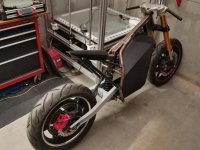
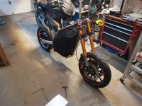
Also took the bike outside to see how it looks like from a distance. So far I really like it, it's weird but it looks fun.
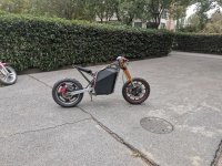
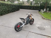
I received almost all the necessary hardware to get the bike running, yay!
New handles:

New brake pumps:
(these are "chinese versions" of brembos, so that was dirt cheap, but they do feel like really nice quality, it was a good find)


And, last but not least.... The massive Kelly KLS72701 Controller!

This controller features variable regen. I'd like to try using it, but I'd like to limit it to a relatively low level in order not to mess up the battery too much. Also, I'd like to keep the hydraulic brake for obvious reasons.... But Ideally, I'd like to operate both of these with one single lever.
So I had this weird idea I'm gonna test: using a clutch actuator to command a cable throttle. I'll parallel the rear brake system to this little actuator. The idea is that whenever I press the lever, brake fluid will first push the actuator since there's very little resistance there, moving the potentiometer until it reaches the full stroke of the actuator. Then once the actuator is maxed out, pressure should increase more and more until the brake pads press the disk.

In theory this should work, but I'll have to reduce the internal volume of the brake pump cylinder in order to use less lever travel to max out the potentiometer.
Anyway, I'll try that, hopefully that will work.
Also working on a sytem to better enclose and connect my ANT BMS. This BMS is really nice, but the main flaws are that it doesn't come with an enclosure, and also you have to solder the power wires directly on it, which I find extremely unconvenient.
So I bought a 100x100mmx4mm pure copper plate, and used my trusty hack saw + file to create those two bus bars.
They will be soldered to the BMS terminals, and then I could just use a screw to secure the power wires to it.


I'm in the process of designing a 3D printable enclosure for it, hopefully it should be nice.
Now that I received the controller, I can finally check how to actually fit all this hardware into the bike. So far, I'm leaning towards this configuration, which is very compact and gives the lowest possible center of gravity, while making everything super accessible and using very short power wires. No real downside aside that it will make cooling the controller a little bit more complicated, but that something I can easily fix with an air scoop on the bottom of the bike, or even later with water cooling if it turns out to be necessary (but it won't).


Now I need to replace this cutting board wih a metal bracket, probably some CNCed aluminum. The battery will be secured in place by pressing it from the top using a metal plate. I'm thinking of using either rubber mats or velcro bands to totally constrain it and forbid any kind of side movement. Simple, cheap, lightweight and probably effective.
Also took the bike outside to see how it looks like from a distance. So far I really like it, it's weird but it looks fun.


mannydantyla
100 W
- Joined
- Dec 4, 2020
- Messages
- 127
That is a big controller, the size is more than I expected.
I just ordered a 4kw hub motor from QS and they're sending me a Kelly KLS7245N controller, which is a bit smaller in dimension than yours, but now I'm starting to wonder if where the mounting location I had in mind will work or not...
More importantly perhaps your controller is over twice as powerful as what QS sold me to be the matching Kelly controller for a 4kw QS hub motor, and yet you said your QS hub is only 3kw.
Makes me question if QS sold me the correct size controller. I simply asked them to provide the matching Kelly controller and I didn't question it as I am still very new to this hobby.
Dui ni shuo de dui
100 kW
mannydantyla said:Makes me question if QS sold me the correct size controller. I simply asked them to provide the matching Kelly controller and I didn't question it as I am still very new to this hobby.
I think QS is right becaue they propose you a safe solution. Meaning thats there is little chance for you that anything will go wrong, it should be reliable. I think it is a bit in the weak side of what they could have proposed, 350 or 400A per phase would have been better and still safe enough.
In my case there is a good chance I'll blow up the motor. My experience tells me that these 3KW hub motors are surpizingly tough, but there is a limit to what they can tolerate, and I just happen to hope that this limit is higher than what this controller can provide.
I guess we'll see...
SlowCo
1 MW
Although that controller is so large it will probably never overheat without burning out the motor first, why not rotate the controller so that the aluminium cooling plate is facing the front of the bike and thus the air flow when riding? You could weld tabs/strips to the front down tube to mount the aluminium cooling plate of the controller to the frame. And then the connecting points face the battery side and are better protected from the elements (water splash from front tire). just a thought.
Dui ni shuo de dui
100 kW
SlowCo said:Although that controller is so large it will probably never overheat without burning out the motor first, why not rotate the controller so that the aluminium cooling plate is facing the front of the bike and thus the air flow when riding? You could weld tabs/strips to the front down tube to mount the aluminium cooling plate of the controller to the frame. And then the connecting points face the battery side and are better protected from the elements (water splash from front tire). just a thought.
Well that was my first idea, but there are four inconveniences in doing this:
-First, I still need some kind of way to secure the batteries in place, so that big plate going from bottom to top will be there anyway
-Second, it is much easier later for maintaining the wiring, I can tighten the phase wires without having to take out the controller
-Third,it makes designing the external enclosure easier, since the narrow part of the controller will face towards the front, allowing for more design options.
-Fourth, orienting the controller this way only makes sense if there are openings in the front of the battery box to provide some cooling air. But I'd like to avoid having any air intake on the front of the box, for bot a cleaner look and also because it usually gets dirty real quick. Plus the box will be much easier to mold out of carbon fiber this way, no need for several mold parts, only one could do the entire half.
I'm not worried about water projections since the enclosure will entirely cover the front, without any way for water to directly enter. Plus the bike isn't intended for riding under the rain anyways.
For cooling I have several options, but so far my plan will be to make a little air scoop on the bottom of the bike, redirecting air upwards between the controller fins and the battery, hopefully cooling both at the same time.
So yeah, took me a long time to come to a decision on this one, but actually this orientation really has no downside as long as the scoop can provide enough air. And as you rightly said, the controller is not likely to heat too much with this motor.
Dui ni shuo de dui
100 kW
Still working on the BMS:
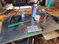
First I soldered the big copper bars. It wasn't as difficult as I thought it would be, I just heated the bars with a blowtorch, heated the BMS with my 100W soldering iron, used plenty of flux and well it worked just fine:
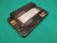
Next I designed and printed a first version of an enclosure to see it it would fit:
I wanted to have more cooling on the balancing side since on my other motorbike the BMS often reaches the limit of 60 degree during summer while balancing, So I found a big heatsink I had collecting dust in a drawer:
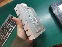
I cut it to size with a hacksaw, which took forever:
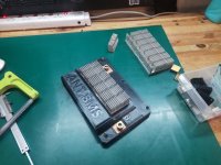
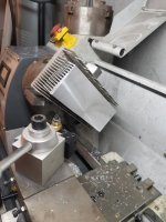
Then I had to machine flat the bottom... But I don't own a milling machine so I had to find another way. Well, basically, a lathe is a milling machine, the difference being that it's oriented horizontally and that the part rotates instead of the tool. So the idea was to use the lathe.
But then I had a very hard time to secure the part, so I found a very sketchy way of "securing" it by just pressing the radiator and the scraps I cut together firmly....
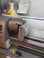
And it worked!
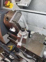
I had to take very shallow passes in order for it not to shift, so it took a long time, but it worked really well, the surface finish was really nice!
Next thing was to work on the internal wiring:
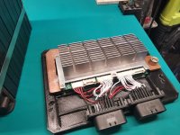
I'm using very high quality automotive connectors this time, they are a bit bulky but they are very reliable.
Also wired one of the battery blocks, including two temperature sensors per block:
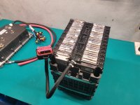
And wired the controller:
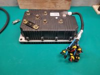
So now I just have to wire the second battery block and to finish some details on the BMS enclosure (I printed a new top cover, slightly bigger to accomodate the plugs), then basically all the electrics will be ready to be installed on the bike!
Next steps will be to design and build the bracket system for securing the battery, the controller and the BMS. So far I have some general ideas as to how to make these, but I'm not totally clear on the details, so that might be a lot of work.
Stay tuned!
First I soldered the big copper bars. It wasn't as difficult as I thought it would be, I just heated the bars with a blowtorch, heated the BMS with my 100W soldering iron, used plenty of flux and well it worked just fine:

Next I designed and printed a first version of an enclosure to see it it would fit:

I wanted to have more cooling on the balancing side since on my other motorbike the BMS often reaches the limit of 60 degree during summer while balancing, So I found a big heatsink I had collecting dust in a drawer:

I cut it to size with a hacksaw, which took forever:

Then I had to machine flat the bottom... But I don't own a milling machine so I had to find another way. Well, basically, a lathe is a milling machine, the difference being that it's oriented horizontally and that the part rotates instead of the tool. So the idea was to use the lathe.
But then I had a very hard time to secure the part, so I found a very sketchy way of "securing" it by just pressing the radiator and the scraps I cut together firmly....

And it worked!

I had to take very shallow passes in order for it not to shift, so it took a long time, but it worked really well, the surface finish was really nice!

Next thing was to work on the internal wiring:

I'm using very high quality automotive connectors this time, they are a bit bulky but they are very reliable.
Also wired one of the battery blocks, including two temperature sensors per block:

And wired the controller:

So now I just have to wire the second battery block and to finish some details on the BMS enclosure (I printed a new top cover, slightly bigger to accomodate the plugs), then basically all the electrics will be ready to be installed on the bike!
Next steps will be to design and build the bracket system for securing the battery, the controller and the BMS. So far I have some general ideas as to how to make these, but I'm not totally clear on the details, so that might be a lot of work.
Stay tuned!
Attachments
Dui ni shuo de dui
100 kW
kuoppis said:That BMS enclosure looks really neat! Is it also waterproof?
Yes, I plan to waterproof it using some automotive silicon gasket. It's not necessary since it's not supposed to see rain, but better safe than sorry!
Dui said:kuoppis said:That BMS enclosure looks really neat! Is it also waterproof?
Yes, I plan to waterproof it using some automotive silicon gasket. It's not necessary since it's not supposed to see rain, but better safe than sorry!
Yes i agree! Better have good waterproofing so no need to worry about rainwater splashing and ofcourse you need to wash your precious bike once in a while :wink:
SlowCo
1 MW
Wow, where do you find the time to do so much work in a few days? Great work again! :thumb:
Dui ni shuo de dui
100 kW
Well it as the weekend, so I had some spare time, plus I spend most of my evenings in the garage during the week. :wink:
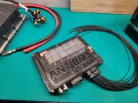
I made some interesting progress those past two days. First, I finished the BMS enclosure. I'll just have to add the wires for the screen later, but aside from that it is finished. I really quite like my design, it will be really convenient to install in the bike and to maintain.
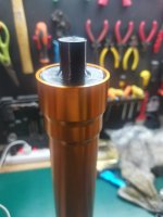
Also, I finally removed the ugly orange anodization from my fork tubes. I followed your great advices and everything went well!
First I 3D printed some plugs and used silicon to prevent water from entering the fork.
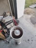
I then plunged the fork tubes in a big PVC pipe filled with a mixure ot sodium hydroxyde, then waited for 20-30 minutes,
Finally, cleaned the parts with water and then a bit of brass wire wheel to get a mate finish....and well, here are the results:
Before:
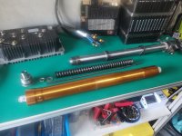
After:
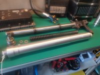
I'm super happy with how they look, that's just so much better than before, almost like new!
I installed back everything on the bike just to see, I really like it, it looks so much better now!
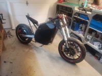
I'm not decided yet for the final color of these tubes, I might go with gunmetal gray, but that's the last thing I'll do on this build, I'll finish all the other stuff first.
I made some interesting progress those past two days. First, I finished the BMS enclosure. I'll just have to add the wires for the screen later, but aside from that it is finished. I really quite like my design, it will be really convenient to install in the bike and to maintain.

Also, I finally removed the ugly orange anodization from my fork tubes. I followed your great advices and everything went well!
First I 3D printed some plugs and used silicon to prevent water from entering the fork.

I then plunged the fork tubes in a big PVC pipe filled with a mixure ot sodium hydroxyde, then waited for 20-30 minutes,

Finally, cleaned the parts with water and then a bit of brass wire wheel to get a mate finish....and well, here are the results:
Before:

After:

I'm super happy with how they look, that's just so much better than before, almost like new!
I installed back everything on the bike just to see, I really like it, it looks so much better now!

I'm not decided yet for the final color of these tubes, I might go with gunmetal gray, but that's the last thing I'll do on this build, I'll finish all the other stuff first.
SlowCo
1 MW
Gun metal gray should suit the bike well. But if you leave them as they turned out now is also great. Much better than the gold!
JimVonBaden
100 W
No matter what, make sure you at least clear coat them, or they will begin to corrode.
Similar threads
- Replies
- 22
- Views
- 2,036
- Replies
- 31
- Views
- 967
- Replies
- 11
- Views
- 745
- Replies
- 4
- Views
- 416
- Replies
- 0
- Views
- 194


