ELECTRIC TRANSMISSION DELTA /WYE and SERIE/PAPALLEL stator

methods said:
<snip>

Lets see: With the CA you could:

* Shift up at a certain speed
* Downshift at a certain current
* Run one winding for the first half of your battery pack and another for the second half to maintain top speed.

Voltage, current, or speed.
(just not all three at once :mrgreen: )

Alright Fechter..... Get to work :!:

-methods

methods,

what dou you mean with that last line "* Run one winding for the first half of your battery pack and another for the second half to maintain top speed."
i don't follow.

rick
 
Say you have a battery pack:

HVC = 50.4V
LVC = 36V

When you are fresh off the charger the top speed is much greater than when you are near the end of the pack.
Between HVC and LVC there is a 29% drop in Top speed.

Say:
30mph at HVC
21mph at LVC

Someone who rides at a steady top speed may want to use the lower KV winding for the first half of the pack and the higher KV winding for the second half of the pack.
To do this with the CA:

Set LVC somewhere in between those two voltages and you will be able to maintain a similar top speed.

This would only be desirable for someone who rides at Steady State Top Speed.
This functionality would be counter productive for someone who accelerates a lot... Battery voltage sags under acceleration and the last thing you would want to do would be to shift into a higher gear :roll:

I thought of this the other day while riding with traffic. I was near the end of my pack and I could barely keep up at 25mph. It was not an available power issue, but simply a free-wheel voltage issue. I would have liked the ability to freewheel at a higher speed.

Does that clear it up?

-methods
 
I just got my 9C motor today!
and I get my bike next week, battery from china... now there I don't know

but anyways...
i unscrewed the screws on the wire out side to pop the side open and start wiring for phase switch but the motor doesn't want to open easily

Suggestions?
or should I just shove my chisel in there....
 
Things we still need to know:

1)
If the phase wires are disconnected while you are moving (free or under power) and then reconnect after say 25ms, will any damage come to controller or motor?
This was discussed but I don't remember it being decisive.

2)
Is there an optimum rpm to shift at to delta or star and how can one figure this out?
a) for maximum efficiency
b) for causing no damage to controller or bike
 
caleb7777 said:
Things we still need to know:

1)
If the phase wires are disconnected while you are moving (free or under power) and then reconnect after say 25ms, will any damage come to controller or motor?
This was discussed but I don't remember it being decisive.

2)
Is there an optimum rpm to shift at to delta or star and how can one figure this out?
a) for maximum efficiency
b) for causing no damage to controller or bike
cycle analyst to see when you are most efficient. It will differ for each motor and bike though, so I really think it's something you will have to figure out your self.
 
Things we still need to know:

1)
If the phase wires are disconnected while you are moving (free or under power) and then reconnect after say 25ms, will any damage come to controller or motor?
This was discussed but I don't remember it being decisive.

The best is to release the throttle while switching from one mode to the second mode.
I did both situation... switching phase wire while moving and when the bike was not running. Dammage to the controller may appear if you switch while the current is very high... ( voltage spike that mosfet dont like may occur as current is higher)

having high mosfet voltage tolerance.. like 4310 and 4110 will help... but i would not recommand having battery voltage too close to that... ex: i did use 75V battery on my 100V fet controller .. and i think this is borderline.

you must pay particular attention when you go back to the wye... cause the rpm of the motor will be higher when in delta than in wye.. so the voltage of the motor may be higher than the battery voltage.. so if you have 75V battery.. ad that you are at max speed, you may get more than 100V generated by the motor when going back to WYE...

ex: max speed reached at 75V in WYE:60km/h
switching to delta will increase speed around 80-85km/h

BUT if you are at 85kmp in delta and switch back to WYE, at that speed and having WYE the voltage will be above 100V...

when you run in delta You MUST wait until the speed is reduced to the point where the WYE max speed is reached to switch back to WYE.

caleb7777 said:
2)
Is there an optimum rpm to shift at to delta or star and how can one figure this out?
a) for maximum efficiency
b) for causing no damage to controller or bike

A) for max efficiency you should switch to delta at the speed where you begin to loose acceleration... it is always a point where from 4-5km/h from the max speed you dont have any considerable acceleration and will reach your max speed slowly... this is because the back emf produced by the motor correspond to a very low voltage difference between the motor and the battery voltage and the current decrease naturally... so acceleration NEED current.. so to get more current at that max speed, you need to switch to delta.. current will increase and will make your bike accelerating again.

B) for causing no dammage or reducing risk of dammage, i would not recommand to switch in delta when your WYE speed is still between 0 and 60% of your max speed in WYE..

ex: speed range in normal WYE: 0 to 60km/h

safe WYE speed to switch to delta: 40 to 60km/h


Doc
 
Those are all very good recommendations, Doc.

As for the right time to shift up from wye to delta, I would think that it would be OK to do this as soon as your battery current starts droping from it's max value when the throttle is wide open. This is the time that Doc describes as "the speed when you start loosing acceleration" in wye mode.

I can't wait to try this mod on my old golden motor hub, and also add some serious air cooling to it while I'm at it. If it survives the operations, I'll do the delta/wye mod to my NC motor this summer to observe efficiency difference between 1 speed and 2 speed setups. As far as I gather, global system efficiency increase will probably be a few percent, and only if the right shifting points are chosen.

And of course I'll be programming these parameters into my controller so it can shift back and forth automatically, but we have to figure out what parameters are to be used in choosing when to shift. I know current alone isn't enough, and motor speed alone either, so it will likely be an equation with these two parameters that will give us the best shift points... so If we can figure out what words best describe the shifting behavior, I can translate that into C code for my PIC. It is already aware of both the current and speed at all times, so it would be easy work to add in a code block that would switch the D/W relays. I have a hunch that there will be another parameter in this equation too that will act like a performance modifier (although I'm not sure this will needed). It could be programmed to be more agressive for performance mode, or more conservative for efficiency mode. Maybe some of you guys that like cars could figure out some of these things since there are many similarities?
 
If you're going fast in delta and switch to wye the BEMF of the motor may be above the pack voltage, but what would happen is you would get a sudden braking effect (regen) until you slow down to the point where the voltages match. Normally, the controller would circulate the regen current back to the batteries. If the battery ESR was too high, then you might exceed the volt rating of the controller.
 
I have been staring at the inside of my hub motor for some time todayand have come to the conclusion that I do not want ot try and fish new wires through there.

I am thinking of gutting the inside so that the relay i have can be in there, with coil on one side of the inner wall and contacts on the other side, sort of.
it's risky but after thinking about it there is no structural integrity dependant on the inner section. The bikes weight lies purely thru the side covers and axles. All the inner plate does is keep the coil lined precisely
and of course it takes a lot of torque.

but that is distributed through it evenly and i figure i can open a decent hole in there without it ever affecting anything as long as I stay away from the side and center walls so that it remains rigid.

I would have to cut out quite a bit and I would probably have to wait until I could get back to my shop in another city but it is possible.

I could also split the relay and glue each half of the relay to either side with very minimal cutting however I would have to use a glue that is amazing.

Do you know of a glue that could take the heat in there and remain very stiff and hold everything forever? If so i am good to go! but I need to know what kind of glue is the ABSOLUTE best.
It needs to be PERMANENT and support the relay perfectly straight!

How hot can the inside get?
 
caleb7777 said:
How hot can the inside get?

my X5 get around 165 celsius max but i try to keep it under 135-140.

Doc
 
I have a relay question. If I want the max battery current to be, say 75A, how much current does each relay' contact need to be able to handle? I need to get some relays to test my 6-wire 3210-12t.

Pat, as long as you are doing a whole new controller, is it even feasible to consider integrating the whole switching function in the controller itself? If so, I think you really will have come up with a "better mouse trap", and I will lead the world in beating a path to your door. :mrgreen:

-- Gary
 
I am leaning towards JB weld. I personally have no experience with JB weld but I know it cures rock hard. The only thing that concerns me is will it ever get soft or fall off?
I googled it and many find it useless on high heat (mufflers) because the adhesion fails but that is significantly hotter than a hub motor right?

If the max temp ever in a 9C motor is 150-165 Celcius then I am assuming it will hold.

Anyone care to agree or disagree?
 
Shifting can be done with a combination of rpm and amp. 60% of max rpm in wye mode is a good reference because max power has passed. This could be raised higher to prevent a large surge in Delta mode. Each motor, controller, and voltage will require different settings for amp draw and max RPM. Having the ability to sample and grab max RPM in Wye mode will be key.

EG


RPM
If rpm is under Z% of max in Wye mode, then Goto Wye
If rpm is above Z% max in Wye mode, then Goto AMP
If RPM is above 100% of Wye mode, do not Goto Wye

AMP
If amp is above X, then goto Wye
If amp is below X, then goto Delta


Amp draw should also be averaged over 2 or 3 seconds. This way little jabs of throttle, bumps, wind or weight shifts won't trigger a Mode change.

X will be different for every setup. We could choose a max amp draw for a particular motor in Delta and plug it in. For a bafang, it could be 30a. The problem will be hills where it doesn't pull enough in Wye mode to depress the wheelspeed, but delta pulls too much current. The controller would bounce back and forth between the two. If this is a problem then the RPM % could be set higher (like 80%) or the Amp draw (X) could be set lower.
 
JBweld is fairly brittle. It should work fine if the there is very little flexing on the mating surfaces. Also, make sure you rough up the parts with sandpaper, and clean them really well before using the JB.
 
Yes, cleaning the surfaces completely is very important no matter what adhesive you use. The motor parts tend to be covered with an oily film.

Silicone RTV is another option. It does not have the tensile strength of JB Weld, but it is flexible and can withstand extremely high temperatures. Make sure it cures completely (24hrs) before closing the motor up to avoid corrosion from the fumes.
 
OK, I gave up.
not because I can't, but because I don't know of a glue that I can trust 100%

i don't want to be riding and have the relay fail inside the hub

I ran the 6 wires but they got scraped up and I am concerned some may short down the road. i may change them again.

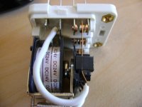
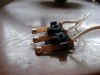
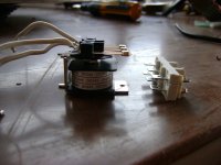
But here are the pics of what I did to my relay so that I could mount it inside the hub.
 

Attachments

  • DSC00056.JPG
    DSC00056.JPG
    25.7 KB · Views: 2,408
  • DSC00070.JPG
    DSC00070.JPG
    46.6 KB · Views: 2,405
  • DSC00071.JPG
    DSC00071.JPG
    48.5 KB · Views: 2,404
  • DSC00072.JPG
    DSC00072.JPG
    52.9 KB · Views: 2,406
And here is what it would have looked like relative to the 2 black steel ribs inside the motor....sort of

You see it would not have taken much of a hole for the coil and a slightly larger hole on underside plate because the coil would have had to rest on bottom of upper for contacts to line up

Sorry I didn't have any black cardboard handy :D
 

Attachments

  • DSC00073.JPG
    DSC00073.JPG
    47.3 KB · Views: 2,406
  • DSC00075.JPG
    DSC00075.JPG
    67.1 KB · Views: 2,405
So if we used a CA to make the switch using the over ride line then we will probably want custom 'PSGain' and 'IntSGain' values in the CA.

@ methods
Any recommendations that would would allow the over ride line to go to ground very fast (we are switching, not ramping up/down) and that would have a slow sensitivity so that it wasn't trying to go back and forth between wye/delta. if you were holding a speed

ideally if i set it at 35kph we would want it to shift up at say 37-38 and down at 32-33 or something like that so that it is always one or the other
 
You have to tune it to be under-damped.
I think you will find that keeping the system properly damped will not be that hard, here is why:

Normally you have 3 states:

Over Damped: Slow smooth response with lag
Under Damped: Near instant response with some overshoot
Oscillation: Bouncing off the walls

Lucky for you, these rules dont apply! :mrgreen:
The reason that a system would experience overshoot is because it has feedback
Your system is running open loop. :wink:

If you are on the throttle going WOT, then you hit the speed limit, if the software is under-damped then you would instantly slow down too far... Which would put you under the speed limit, which would cause the CA to hit the gas too hard, which would put you over the speed limit, bouncing back and forth. get the point?

In this case, when you hit the speed limit, instead of the bike slowing down, IT WILL SPEED UP!
This will cause the CA to keep pulling DOWN in the CORRECT direction so what you will find is that your system comes out with the best of both worlds:

Uber over damped and lightning fast.

Does this explain it for you?

So you can tune those to be as fast as you like and there is no chance for oscillation.

-methods
 
Yes it will work great!

What I am wondering is what will be the effect of changing the values of 'PSGain' and 'IntSGain' in CA

PSGain default: 0.08 Range:0-.99

IntSGain default:200 Range:0-999

If I am correct these 2 values control essentially all the speed related override stuff
 
The CA instruction manual is pretty clear on this.

http://www.ebikes.ca/drainbrain/Cycle_Analyst_Manual.pdf

8.7 PSGain
This is the Proportional Speed Gain for the over-ride output. It can
decrease the response time and reduce overshooting the set point
speed, but at the risk of causing rapid vibrations if it is too high. The
range can vary from 0 to 0.99 V/kph or V/mph. Default = 0.08

8.8 IntSGain
This value determines how rapidly the over-ride output will ramp down
when the speed of the vehicle exceeds the limit speed. Increasing this
value will speed up the response time for the speed control, but at the
risk of causing oscillations. Too low of a value will allow considerable
overshoot of the speed limit. The range of values is from 0 to 999, and
the scaling is currently arbitrary. Default = 200

Set PSGain for 0.99 for the fastest response
Set IntSGain for 999 for the fastest response.

I just presented an argument for why you can ignore the caveats.
Your system is Open Loop.

(actually it is not open loop, but the feedback is always in the advantageous direction, so you can think of it as open loop)

-methods
 
Back
Top