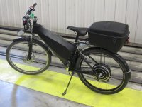
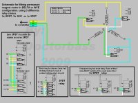
ELECTRIC TRANSMISSION DELTA /WYE and SERIE/PAPALLEL stator

TylerDurden said:
ZapPat said:
BUT, as for the 36V/72V battery switching figures, I can't see how this would help much with efficiency. The only advantage I can see is that the controller will be saving it's PWM losses if doing low speed cruising at 36V, versus doing 50% PWM at 72V. That's a few percent efficiency gain at most - more for crappy slow switching controllers, less if the controller has low switching losses.
This question has been bugging me for awhile...

At 50%PWM, phase current is roughly the same as 100%PWM ?

But voltage (and power) are effectively halved; so I2R losses are proportionally 2x, compared to 100%pwm?


At 50% PWM for 72v and 100%PWM for 36v, and the controller at the same battery input power limit, the phase current (the only current that matters to the FETs and motor) will be ~2x that of the 36v setup at 100%. This should mean about 4x the losses for the 72v setup, but it's delivering twice the torque and power (and drawing twice the power of course).

Ideally, picking a voltage/wind combo that lets the controller be 100% duty cycle at your intended cruise RPM would make for the least heating in motor and controller, and better efficiency operation.

Picking a lower-turn-count motor to run with higher voltages results in equal torque too a higher turn-count motor (if copper fill is equal), but to do this is needs the PWM to be multiplying the current by the ratio of the difference in turns. So, the disadvantage is the controller heating/abuse, the advantage is a wider speed range that the motor can sustain a given torque value.
 
ZapPat said:
I'm not sure I believe all these statements. For one, I can't see how using a "409" wound motor in "406" mode (only using 2/3rd of the coil lengths) would help in any way with efficiency...


it is good that u don't believe him, i didn't either at first.

each turn count has it's peak efficiency at a different rpm.
taking it to it's ultimate, imagine if u could switch from 401 thru to 4013 in one turn increments.
select the proper winding with the so called 'sweet spot' that's closest to the desired speed/torque requirement.

the closest thing that i'm familiar with it's like staggering a series of pass filters each increasing an octave centre freq to achieve an overall wider bandwidth.
perhaps that's not the best analogy, could show me where my thinking has gone astray?
maybe it's more like a variac.
 
But it's not the same as having two different windings with an equal amount of copper in, even (as Delta/Wye is equivalent to). It's a tapped winding, so efficiency is down the pan for the lower turn count............
 
yes copper fill would ideally remain constant so the 4-series isn't the best example.
just using the wind-count taken to an extreme level as illustration if a motor had separate single turn construction.
even with the reduced fill it would seem there's a benefit to simply having available a lower bemf winding.

also bob bcmcree tried pursuing this & was trying to get his hands on a older version dual-wind 4-series.
maybe he can confirm but iirc all the present day dual-wind xlyte are tapped whereas the really old ones actually had multiple winds which is the kind bocabikeguy was using supposedly.
bob posted a request but abandoned the idea when he couldn't find an old one to try as duals are rare enuf to begin with.
 
liveforphysics said:
At 50% PWM for 72v and 100%PWM for 36v, and the controller at the same battery input power limit, the phase current (the only current that matters to the FETs and motor) will be ~2x that of the 36v setup at 100%. This should mean about 4x the losses for the 72v setup, but it's delivering twice the torque and power (and drawing twice the power of course).
LFP - There might be a typo there, since equal power inputs to the controllers will yield equal power outputs. So with both systems at the same motor speed (and thus equal BEMF), they will be delivering the same output current to the motor... thus equal losses (minus extra controller switching losses and motor PWM losses at 72V). I do of course agree that 2X the power means 4X the losses, which is why I find my 2WD bike is often more efficient than my RWD bikes. At a certain motor current the squared system power losses will overwhelm the extra losses introduced by a second motor/controller. If doing lots of hard acceleration with high current limits, and/or lots of hill climbing and/or load pulling, then it is easy to take advantage of the reduced I^2 losses of two motors. Another factor to consider is the motor's magnetic saturation, which is only about 100A phase current for a typical 9C hub. After this point, you are getting much reduced return from your motor so it gets even better then to split the power up between two motors in this case.


liveforphysics said:
Picking a lower-turn-count motor to run with higher voltages results in equal torque too a higher turn-count motor (if copper fill is equal), but to do this is needs the PWM to be multiplying the current by the ratio of the difference in turns. So, the disadvantage is the controller heating/abuse, the advantage is a wider speed range that the motor can sustain a given torque value.
True, but you'll only get equal startup torque for both motors IF your controller can dish out the extra phase current that the lower turn count motor needs to produce the same torque (and watch out for melting phase wires too with those higher kV motors). If we had small, powerfull and highly efficient controllers on our bikes we could just choose a real low turn count motor with big phase wires, and then we would enjoy a non-speed limited, AND non-stall-torque limited EV experience! :D


Pat
 
TylerDurden said:
ZapPat said:
BUT, as for the 36V/72V battery switching figures, I can't see how this would help much with efficiency. The only advantage I can see is that the controller will be saving it's PWM losses if doing low speed cruising at 36V, versus doing 50% PWM at 72V. That's a few percent efficiency gain at most - more for crappy slow switching controllers, less if the controller has low switching losses.
This question has been bugging me for awhile...

At 50%PWM, phase current is roughly the same as 100%PWM ?

But voltage (and power) are effectively halved; so I2R losses are proportionally 2x, compared to 100%pwm?

TD - In my example above I was comparing two identical low speed situations, but one using a 72V battery and the other using a 32V battery. In each case the controller's I/O power is the same, but the 72V situation has to do 50%duty PWM to match the 32V controller's output. Output current and voltage will essentially be the same, although there is PWM pulsing present in the 72V case. So the 32V mode would save a few percent losses in the controller from avoiding switching losses. I did not mention in my previous post that there will also be reduced losses in the motor itself in the 100%duty 32V case while cruising at WOT, because of slightly reduced magnetic losses from avoiding PWM in the motor coils.

However, an equivalent 72V system doing 50% PWM will have one advantage I can see: half the battery side current. So this reduces battery wire losses by four times (2^2) for the 50%duty 72V system as compared to the 100%duty 36V system. This is probably less than the losses though, so there would still be a net benefit with the 36V system at WOT. But... is all the battery hastle worth the extra few percent efficiency points gained, and this only during the times we are cruising at the equivalent of our vehicule's half throttle position with no current limiting going on? I'd go with D/W switching only first, and might consider adding battery S/P switching to this only for a very extreme drag setup.
 
The only efficiency graphs I've seen where somebody measured the efficiency at various duty cycles indicate you take quite a hit in efficiency when running at less than 100%. The difference is more if you have a lot of loss in the phase wires (long wires) since they are running at a higher current and losses are proportional to current squared.

With a permanent magnet motor, the BEMF limitation on top speed is always a drawback.

What would be nice is a small but efficienct induction motor. This will behave much like having infinitely variable motor windings on a PM motor. Induction motors have a wider RPM range than PM motors.
 
i have used the dual mode crystalyte motors since pretty much the beginning. the idea came from some guy in toronto who got the original motors custom built. his name escapes me. he did his order through Joshua Goldberg of EV Solutions. Kenny the owner of Crystalyte liked the idea and began offering the motors in a couple of different configurations. a chap in the UK called Steve Head got ahold of one and built an amazing bike called the dirt-monkey with one. he is also the one who came up with upping the voltage to 72V and using it on a tiny 20" wheel to improve torque. i bought a 406/409 (which i resold to Ypedal. it was his first hub motor) and a 409/4011 front. these were both from the 4th or 5th batch of these dual mode motors ever. the motors were never Delta/WYE. they were always a tapped WYE.

bocabike in florida bought his motor around the same time as i bought mine. so his was also a tapped wye. some one on some forum comparded the tapped wye to being like a Delta/WYE except with simpler wiring. and just like an urban legend the myth of the Delta/Wye grew. i gues it was either an easier concept or it was a catchier name. and now everyone believes in the mythical original Delta/Wye. in discussions contrributors started describing the taped mode as the DELTA mode and the full turn count mode as the WYE mode.

rick

i think his name was Bernstein or something like that. he's the guy who used to fix the crystalyte motors in Canada back in pre-history. anyways he's the one who started the tapped winding or dual mode crystalyte motor thing.
 
rkosiorek said:
while cleaning some stuff out of my storage unit i came across part of an old experiment. originally this was planned for rear drive wheel of an electrathon tadpole trike. so far i only came across one of the stators. but i'm sure that i will eventually find the covers and rotor/rim.

since for some reason the Crystalyte X5 works pooly as a Delta-Wye i tried a different route. this 5302 was re-wound so that there are 2 windings on each pole with 2 turns each. if i take the 2 windings and connect them in series i end up with 4 turns (2 + 2)per pole and a 5304 motor. if i connect the same windings in parallel i end up with a 2 turn motor with heavier windings. now bringing out 12 wires through the bearing is sort of impossible, so i wanted to add internal relays to do the switching. the result is this 5304/5302 Series/Parallel motor.

View attachment 2

it actually takes 6 relays. in this early motor i used 30A automotive control relays. i had to enlarge the open areas in the stator slightly to make room for them.

View attachment 1

for all practical purposes the relay contacts are in parallel for each phase. 2 relay contacts in parallel carry the load. this effectively doubles the current carrying capacity of a single relay or approx 60 amps at the rated 28VDC for the pair. the AC rating would be higher as any arc is suppressed with each reversal of the AC phase voltage. as with all contacts the carry current is much higher than the switched current. meaning that it should be safe to use with a 50/60 amp controller at 48V. although i have not tortured these relays as severly as steveo or the good DoctorBass might and they had very few miles on them, so far they have worked reliably.

this was my first attempt. the refined version used 50A hermetically sealed "marine" relays. but that stator is still buried somewhere in storage. when i find the rest of the parts for the motor i will add a couple of pictures.

rick

Hey Rick

The time has finally come and i will be getting my new 5303 motor this week; I want to ask if you could post a SIMPLE diagram in regards to how to wire the relays into my x5, all i really need to know is how you did one of the phases, and i will repeat the process for all of them

from what i understand ... or remember... i have to parallel the 5303 winding to achieve 5306; Does that mean the relay have to be ok for my motor to do 5306 mode ? ... or do the have to be off to achieve 5306 mode ... so many question... so anxious to get this working ..hope you could help ..

I've bought the relays as per docs post a while back .. the bosh 80 amp automotive relays!! if i do 2 in parrallel .. i should easily to 160amps :O...@ 144v .... WOWWW....

file.php


file.php


thanks
-steveo
 
Steveo,

i already posted the schematics a couple of pages back. but here they are again.

series parallel-p.jpg

for higher res - go back a couple of pages.

rick
 
rkosiorek said:
Steveo,

i already posted the schematics a couple of pages back. but here they are again.


for higher res - go back a couple of pages.

rick


Hey Rick,

I have looked at the previous schmatic; however i am having a hard time understanding how eactly to wire everything up...

I'm not very good with understanding schematics... photos for me are usually best of ... just a simple plan jane paint drawing ....

from when i spoke with you i remember you telling me that x5303 has windings that are in series; all i need to do is make them go parrallel with contractors right?

thanks
-steveo
 
no you have to separate out all of the individual strands of the wiring. all of the strands are presently wired in parallel. you have to sub-divide that one parallel group into TWO identical sub groups. so let us say that your original windings used 8 strands of wire per winding. separate out those original 8 strands into TWO sets of 4 strands each. this is how you get your TWO windings.

once you open up your motor you will be able to undo the wires and see what you got to work with. but your first step is to open it up and separate out the wire bundles. make sure you mark all of the starts (the big knot common to all of the windings) and then separate all of the individual windings. separate out the yellow, green and blue starts. then using one of the windings (pick one yellow, green or blue) subdivide that into TWO windings. do the same for the other colors. now you will have TWO each of the yellow, green and blue windings i makes mine Y1 for Yellow#1 and Y2 for Yellow#2, G1 for Green#1 etc. i also marked them for the start and the end of the winding so for instance Y1S is the start of the 1st yellow winding Y1E is the end of that same winding.

that is it. that is all that you need to know to follow the schematic. i don't have the time or the patience to do this all out in paint or to do detailed instructions. if you cannot picture the difference between series and parallel, maybe this is not the project for you to attempt.

Good Luck

rick
 
rkosiorek said:
no you have to separate out all of the individual strands of the wiring. all of the strands are presently wired in parallel. you have to sub-divide that one parallel group into TWO identical sub groups. so let us say that your original windings used 8 strands of wire per winding. separate out those original 8 strands into TWO sets of 4 strands each. this is how you get your TWO windings.

once you open up your motor you will be able to undo the wires and see what you got to work with. but your first step is to open it up and separate out the wire bundles. make sure you mark all of the starts (the big knot common to all of the windings) and then separate all of the individual windings. separate out the yellow, green and blue starts. then using one of the windings (pick one yellow, green or blue) subdivide that into TWO windings. do the same for the other colors. now you will have TWO each of the yellow, green and blue windings i makes mine Y1 for Yellow#1 and Y2 for Yellow#2, G1 for Green#1 etc. i also marked them for the start and the end of the winding so for instance Y1S is the start of the 1st yellow winding Y1E is the end of that same winding.

that is it. that is all that you need to know to follow the schematic. i don't have the time or the patience to do this all out in paint or to do detailed instructions. if you cannot picture the difference between series and parallel, maybe this is not the project for you to attempt.

Good Luck

rick


Hey rick,

sorry if i don't understand the schematic to well... but i'm fully capable of modding :mrgreen:

i think i understand the concept.... of how it works..

1) remove teflon wires; label phases accordingly...
2) Seperate each phase on the "wye" end yellow/green/blue so each phase has 2 groups of leads divided seperatly... (ex 8 wires in a phase ... make 2 groups of 4) (so i will have 6 phase wire ends to work with...
3)Repeat the same process on the "delta" phase wires end... so i should have

WYE Y1 -- DELTA Y11
WYE Y2 -- DELTA Y22

WYE G1 - DELTA G11
WYE G2 - DELTA G22

WYE B1 - DELTA B11
WYE B2 - DELTA B22

i hope i got this right..

THATS ALOT OF MOTOR LEADS TO WORK WITH LOL

thanks
-steveo
 
your terminology differs from mine. at least i hope you are only using misguided wording.

since this motor will only be wired as a "WYE" your reference ot "Delta" is confusing to me. what i call the winding "START" is what i think you refer to as the "Delta" wire. if that is so then you have got it. but whatever you do or whatever you call them, do not confuse them or mix them up. otherwise it will be very difficult to identify which wire is what just by looking at it.

you will end up with 12 wires altogether going to the relays. that is part of the problem. how do you fit all of that crap inside the covers. have fun.

rick
 
rkosiorek said:
your terminology differs from mine. at least i hope you are only using misguided wording.

since this motor will only be wired as a "WYE" your reference ot "Delta" is confusing to me. what i call the winding "START" is what i think you refer to as the "Delta" wire. if that is so then you have got it. but whatever you do or whatever you call them, do not confuse them or mix them up. otherwise it will be very difficult to identify which wire is what just by looking at it.

you will end up with 12 wires altogether going to the relays. that is part of the problem. how do you fit all of that crap inside the covers. have fun.

rick

yes... alot of wiring ... you did an excellent job on your motor!!!!

sorry for the confusion with ... delta... i will not refer to it that way for an x5... i will call it "start"!!

thanks
-steveo
 
steveo said:
rkosiorek said:
your terminology differs from mine. at least i hope you are only using misguided wording.

since this motor will only be wired as a "WYE" your reference ot "Delta" is confusing to me. what i call the winding "START" is what i think you refer to as the "Delta" wire. if that is so then you have got it. but whatever you do or whatever you call them, do not confuse them or mix them up. otherwise it will be very difficult to identify which wire is what just by looking at it.

you will end up with 12 wires altogether going to the relays. that is part of the problem. how do you fit all of that crap inside the covers. have fun.

rick

yes... alot of wiring ... you did an excellent job on your motor!!!!

sorry for the confusion with ... delta... i will not refer to it that way for an x5... i will call it "start"!!

thanks
-steveo


steveo.. You should post pics of your project!! ( the same you sent to me!!)

really nice job you did.. and You know what... I will do that too i think. I thought about that alot in the past but YOU decided to do it and now that just waked up me about that..!

I have a rear 5303 that need some care!! :twisted:

Doc
 
I'd like to do this mod to my rear 9C, and there are a few things that I'm not completely clear on.

Ideally, what I would do :

- get 3 50Amps automotive spdt that I'll put inside the hub (are they going to be fine with 52V ?)
- replace all the phase wires with teflon high temp wires (someone here mentioned that, seems like a good idea, given that these wires are not that expensive)
- I need to add at least 1 wire to action the 3 relays, is there a way to get the ground from one of the hall sensor wires, or do I need to get 2 wires out to action the relay ?

On the control side :
- Someone mentioned some electronic card that cuts-off the throttle whenever changing the relay state, I find that fairly interesting in terms of safety, especially with 3 relays rather than a 3pdt, what do you guys think ?
- Has anyone successfully used methods' idea to use the CA for automatic switching? if so, I'd really like to build a board with a 3 state switch that would have "auto" / "wye" / "delta" (sounds like the best of both worlds), I'm not using my CA for current / speed / voltage limiting anyway.
- I'm guessing that an alternative would be to use the speed wire that goes to the CA (I have the DP model), and use that as an input for a board which would have the logic

On the technical side :
What tools do I need to separate the 3 phases that are soldered together inside the hub ?
What kind of soldering should I do between the phase wires and the actual coils ?
 
Looking into doing this WYE/DELTA upgrade on the following system:

- Goldenmotor 36V/500W rear hub motor
- 48V SLA's
- 48V/700W Ecrazyman controller at 28A
- maxed at 43km/h on the flats, average 34km/h

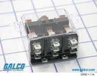
I just want something that would work on my system and I found the following 30A 3PDT:

relay_gp_delt_375tm_3pdt_p.jpg
30 amp at 300VAC 80% PF
15 amp at 600VAC 80% PF
30 amp at 28VDC
12V DC Coil

http://www.galco.com/scripts/cgiip.exe/wa/wcat/itemdtl.r?listtype=Catalog&pnum=21014-81-DELT

Q1. Anybody see any problem with this working on my system? Found a few on eBay for ~$16US.

Q2. Am I correct in thinking that the indicated coil voltage (12VDC in this instance) is the voltage needed to operate the relay? Does it make a difference to have higher or lower coil voltages?

Any input is appreciated, thanks.
 
lucky37 said:
Looking into doing this WYE/DELTA upgrade on the following system:

- Goldenmotor 36V/500W rear hub motor
- 48V SLA's
- 48V/700W Ecrazyman controller at 28A
- maxed at 43km/h on the flats, average 34km/h

I just want something that would work on my system and I found the following 30A 3PDT:


30 amp at 300VAC 80% PF
15 amp at 600VAC 80% PF
30 amp at 28VDC
12V DC Coil

http://www.galco.com/scripts/cgiip.exe/wa/wcat/itemdtl.r?listtype=Catalog&pnum=21014-81-DELT

Q1. Anybody see any problem with this working on my system? Found a few on eBay for ~$16US.

Q2. Am I correct in thinking that the indicated coil voltage (12VDC in this instance) is the voltage needed to operate the relay? Does it make a difference to have higher or lower coil voltages?

Any input is appreciated, thanks.
A1. it should work. as long as you do not exceed the contact limit of 30A for long periods of time. what i mean to say is if you keep the controller stock. the contacts should survive. if you modify the controller for higher current limits you might want to consider looking for a heavier relay.

A2. you will need to find some way to reduce the battery voltage from the 56V or so that your freshly charged batteries will supply down to 12 to 14V that the relay needs. this can be done by a series dropping resistor, a constant current source or a 12V DC-DC converter.

the coil of the relay will work within a wide voltage range. usually relay coils rated 12V will pull in with a voltage as low as 9V. on the upper end the worry is how hot will the coil get? the higher the voltage the hotter the coil. you may be able to get away with 20V but almost certainly not 56V.

rick
 
Thanks rick,

Planning on keeping my system as is right now. If I were to upgrade I'd be getting a whole new bike/motor/controller/batteries, so I'd be selling this one.

I've read this thread and realize that I'll have to be careful with "downshifting" from DELTA back to WYE/STAR; to wait until I've slowed enough to avoid voltage spikes. I'm okay with closing the throttle to up/downshift, and I'll see how it works from there.

Now I'll have to figure out which way to power the 12V coil. Possibly thinking DC-DC converter..

Ordered a relay and will attempt the upgrade when it's in. Thanks again. :D
 
Got the delta/wye conversion up and running and now have a top speed on 55km/h on the flats (40km/h previous)! I'm drawing a lot of constant amps (25-28amps) and my batteries are drained much quicker, but it's a blast so far!

Used 3 x SPDT, 12VDC coil, 30Amp auto relays.

Img_0417-2.jpg
Img_0405-2.jpg
Img_0427-2.jpg


I'm hoping Doctorbass doesn't mind, but I made a few additions to a wiring schematic he added a while back. It was VERY helpful in making this conversion happen and I wanted to say thanks! If you want this removed or see an error Doctorbass, please let me know. I take NO credit for this schematic.

WIRING SCHEMATIC by DOCTORBASS
00 - WIRING DELTA-WYE.jpg
 
Lucky37,
Congrats on your mod! :D

I would like to do one like that too. Your speed improvement looks to be on par, and is very close to what I would like to achieve with my "P0" bike. Can you tell us what your current was before going into Delta please? That way we have the last of the details.

My concern is whether it makes sense to go D-Y, or just throw more current to reach that speed. In other words, does the math pan out? On a 36V system I can see the value of D-Y. If I run 74v though I could always give it more throttle/raise the current limit.
 
36V/500W Goldenmotor
4x12V 10Ah SLA (48V system)
48V/700W Controller

My current in Wye mode at full throttle and top speed (38-40km/h) is around 14-16Amps, while in Delta mode at full throttle and top speed (52-55km/h) is around 26-28Amps. Watts are ~700 and ~1300 respectively. I will have more detailed numbers as I do more testing. The speed gain for me is great, but I have no torque left in Delta mode to really feel the acceleration. More volts would be a good way to go, but I'd still do the Delta/Wye mod on that :D
 
Back
Top