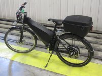
crap, posted the wrong tiny, no idea where that one came from.
sorry, never used one b4, now i know why.
sorry, never used one b4, now i know why.
TylerDurden said:This question has been bugging me for awhile...ZapPat said:BUT, as for the 36V/72V battery switching figures, I can't see how this would help much with efficiency. The only advantage I can see is that the controller will be saving it's PWM losses if doing low speed cruising at 36V, versus doing 50% PWM at 72V. That's a few percent efficiency gain at most - more for crappy slow switching controllers, less if the controller has low switching losses.
At 50%PWM, phase current is roughly the same as 100%PWM ?
But voltage (and power) are effectively halved; so I2R losses are proportionally 2x, compared to 100%pwm?
ZapPat said:I'm not sure I believe all these statements. For one, I can't see how using a "409" wound motor in "406" mode (only using 2/3rd of the coil lengths) would help in any way with efficiency...
LFP - There might be a typo there, since equal power inputs to the controllers will yield equal power outputs. So with both systems at the same motor speed (and thus equal BEMF), they will be delivering the same output current to the motor... thus equal losses (minus extra controller switching losses and motor PWM losses at 72V). I do of course agree that 2X the power means 4X the losses, which is why I find my 2WD bike is often more efficient than my RWD bikes. At a certain motor current the squared system power losses will overwhelm the extra losses introduced by a second motor/controller. If doing lots of hard acceleration with high current limits, and/or lots of hill climbing and/or load pulling, then it is easy to take advantage of the reduced I^2 losses of two motors. Another factor to consider is the motor's magnetic saturation, which is only about 100A phase current for a typical 9C hub. After this point, you are getting much reduced return from your motor so it gets even better then to split the power up between two motors in this case.liveforphysics said:At 50% PWM for 72v and 100%PWM for 36v, and the controller at the same battery input power limit, the phase current (the only current that matters to the FETs and motor) will be ~2x that of the 36v setup at 100%. This should mean about 4x the losses for the 72v setup, but it's delivering twice the torque and power (and drawing twice the power of course).
True, but you'll only get equal startup torque for both motors IF your controller can dish out the extra phase current that the lower turn count motor needs to produce the same torque (and watch out for melting phase wires too with those higher kV motors). If we had small, powerfull and highly efficient controllers on our bikes we could just choose a real low turn count motor with big phase wires, and then we would enjoy a non-speed limited, AND non-stall-torque limited EV experience!liveforphysics said:Picking a lower-turn-count motor to run with higher voltages results in equal torque too a higher turn-count motor (if copper fill is equal), but to do this is needs the PWM to be multiplying the current by the ratio of the difference in turns. So, the disadvantage is the controller heating/abuse, the advantage is a wider speed range that the motor can sustain a given torque value.
TylerDurden said:This question has been bugging me for awhile...ZapPat said:BUT, as for the 36V/72V battery switching figures, I can't see how this would help much with efficiency. The only advantage I can see is that the controller will be saving it's PWM losses if doing low speed cruising at 36V, versus doing 50% PWM at 72V. That's a few percent efficiency gain at most - more for crappy slow switching controllers, less if the controller has low switching losses.
At 50%PWM, phase current is roughly the same as 100%PWM ?
But voltage (and power) are effectively halved; so I2R losses are proportionally 2x, compared to 100%pwm?
rkosiorek said:while cleaning some stuff out of my storage unit i came across part of an old experiment. originally this was planned for rear drive wheel of an electrathon tadpole trike. so far i only came across one of the stators. but i'm sure that i will eventually find the covers and rotor/rim.
since for some reason the Crystalyte X5 works pooly as a Delta-Wye i tried a different route. this 5302 was re-wound so that there are 2 windings on each pole with 2 turns each. if i take the 2 windings and connect them in series i end up with 4 turns (2 + 2)per pole and a 5304 motor. if i connect the same windings in parallel i end up with a 2 turn motor with heavier windings. now bringing out 12 wires through the bearing is sort of impossible, so i wanted to add internal relays to do the switching. the result is this 5304/5302 Series/Parallel motor.
View attachment 2
it actually takes 6 relays. in this early motor i used 30A automotive control relays. i had to enlarge the open areas in the stator slightly to make room for them.
View attachment 1
for all practical purposes the relay contacts are in parallel for each phase. 2 relay contacts in parallel carry the load. this effectively doubles the current carrying capacity of a single relay or approx 60 amps at the rated 28VDC for the pair. the AC rating would be higher as any arc is suppressed with each reversal of the AC phase voltage. as with all contacts the carry current is much higher than the switched current. meaning that it should be safe to use with a 50/60 amp controller at 48V. although i have not tortured these relays as severly as steveo or the good DoctorBass might and they had very few miles on them, so far they have worked reliably.
this was my first attempt. the refined version used 50A hermetically sealed "marine" relays. but that stator is still buried somewhere in storage. when i find the rest of the parts for the motor i will add a couple of pictures.
rick
rkosiorek said:Steveo,
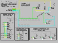
i already posted the schematics a couple of pages back. but here they are again.
for higher res - go back a couple of pages.
rick
rkosiorek said:no you have to separate out all of the individual strands of the wiring. all of the strands are presently wired in parallel. you have to sub-divide that one parallel group into TWO identical sub groups. so let us say that your original windings used 8 strands of wire per winding. separate out those original 8 strands into TWO sets of 4 strands each. this is how you get your TWO windings.
once you open up your motor you will be able to undo the wires and see what you got to work with. but your first step is to open it up and separate out the wire bundles. make sure you mark all of the starts (the big knot common to all of the windings) and then separate all of the individual windings. separate out the yellow, green and blue starts. then using one of the windings (pick one yellow, green or blue) subdivide that into TWO windings. do the same for the other colors. now you will have TWO each of the yellow, green and blue windings i makes mine Y1 for Yellow#1 and Y2 for Yellow#2, G1 for Green#1 etc. i also marked them for the start and the end of the winding so for instance Y1S is the start of the 1st yellow winding Y1E is the end of that same winding.
that is it. that is all that you need to know to follow the schematic. i don't have the time or the patience to do this all out in paint or to do detailed instructions. if you cannot picture the difference between series and parallel, maybe this is not the project for you to attempt.
Good Luck
rick
rkosiorek said:your terminology differs from mine. at least i hope you are only using misguided wording.
since this motor will only be wired as a "WYE" your reference ot "Delta" is confusing to me. what i call the winding "START" is what i think you refer to as the "Delta" wire. if that is so then you have got it. but whatever you do or whatever you call them, do not confuse them or mix them up. otherwise it will be very difficult to identify which wire is what just by looking at it.
you will end up with 12 wires altogether going to the relays. that is part of the problem. how do you fit all of that crap inside the covers. have fun.
rick
steveo said:rkosiorek said:your terminology differs from mine. at least i hope you are only using misguided wording.
since this motor will only be wired as a "WYE" your reference ot "Delta" is confusing to me. what i call the winding "START" is what i think you refer to as the "Delta" wire. if that is so then you have got it. but whatever you do or whatever you call them, do not confuse them or mix them up. otherwise it will be very difficult to identify which wire is what just by looking at it.
you will end up with 12 wires altogether going to the relays. that is part of the problem. how do you fit all of that crap inside the covers. have fun.
rick
yes... alot of wiring ... you did an excellent job on your motor!!!!
sorry for the confusion with ... delta... i will not refer to it that way for an x5... i will call it "start"!!
thanks
-steveo

lucky37 said:Looking into doing this WYE/DELTA upgrade on the following system:
- Goldenmotor 36V/500W rear hub motor
- 48V SLA's
- 48V/700W Ecrazyman controller at 28A
- maxed at 43km/h on the flats, average 34km/h
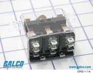
I just want something that would work on my system and I found the following 30A 3PDT:
30 amp at 300VAC 80% PF
15 amp at 600VAC 80% PF
30 amp at 28VDC
12V DC Coil
http://www.galco.com/scripts/cgiip.exe/wa/wcat/itemdtl.r?listtype=Catalog&pnum=21014-81-DELT
Q1. Anybody see any problem with this working on my system? Found a few on eBay for ~$16US.
Q2. Am I correct in thinking that the indicated coil voltage (12VDC in this instance) is the voltage needed to operate the relay? Does it make a difference to have higher or lower coil voltages?
Any input is appreciated, thanks.


