Silver Surfer,
Great stuff man, I've been a bit preoccupied of late and am just catching up...
I looked into the PTFE (teflon) silver clad copper and if my understanding is correct.. the phase power wire (16g) youre suggesting / using is rated MIL and 600v (assuming that's AC rating)? If I understand this right, 15a @ 600v ac is what that equates to?
If all things are equal that would be good for 150A @ 60v - in theory atleast, my sub conscious is bugging me though because it seems that there is some law I'm neglecting which is why it's always best to get your power from voltage rather than current, I fear that the amount of lost power and thus heat (somewhere) will be far greater at 60v than it would be at 600v - please correct me or elaborate / specify the law I am thinking of (it's late).
If I am wrong and lower voltages don't mean lower current handling and thus lower total power:
Wouldn't the optimal solution for a direct drive hub be to have 3 phase leads of 14 or even 12 guage (ptfe) in the same silver clad copper and then internaly wire relays with the same (or less if absolutely needed) to provide the delta/wye switching. This provides largest guage to handle the extended high power (not only on inital launhc but only as torque runs out and noload is approached does the draw drop) needed to drive a direct drive hub up to speed... it also handles the higher voltages of delta mode back EMF nicely and lets be honest the teflon coating is probably the safest and lightest insulation not to to mention the best to work with (I've used it for other projects)
The idea in a geared brushless DC motor would serve the 6 phases out with (required) external switching but here 16 or 14g would be fine because the peak current draw happens very quickly (inrunner spins up to no load fast thanks to gearing so you have 1-3 seconds of high power followed by lower than normal direct drive currents for same kT (torque per amp). Here the bursts of required energy would be so quick they wouldn't even heat the wires I would think that would assist in the extension of life with the relays also (running a geared bldc hub).
I've read this all over as I begin reasearch of a newer MCU controlled but relay (or actuated mechanical contact) that I would like to build for a new project (Dahon Speed Frame - geared bldc hub / 9c dd hub - matching demo bikes) 60-70A and 15S as of now but I may lower that a bit ... my current setup is a infineon with a soldered shunt (too much solder) and 600w rated internal brushless geared hub motor which I push 5.6 hp out of and dash from 0-27 on flat ground in 3 seonds if I can keep the front end down).
The teflon wire (if lower voltge doesn't effect it's handling abilities should be good for a maximum power of 9000w or 12 hp (not too shabby) seems very promising!
I have many 9C here but I've only got the delt wye crudely working on 2 wheels and it's external switching... it's really cool but I just haven't had time until now to get on making this for my 2 main riders / demo bikes.
I think the idea of PCB mounted relays is great but I am also beginning some form of physical hardware style switching mechanism may be the better way to go as opposed to relays... Think beam with gold plug connecters on each side and put it on a sliding mechanism, anchor the NC side with a strong spring pulling it to NC position. Mechanically a cable would pply pressure from the sprung side... this would force all the connectors on the wye side to disconnect the same time the continued pressure ensure the delta contacts make positive connection but only after the wye has been split for sure, this is kinda of mechanical dead zone to ensure no shorts or shoot through events.
Actuating this would be easy... a simple hobby servo - with the "diy contactor" setup to be engaged with the servo in it's 0 position and to engage delta power is applied to the servo and it's position is set to the maximum plug depth on the opposite side of the slide... assuming 2mm thick "moving beam" and 3.5mm connectors plus enclosure (ABS plastic or aluminum but insolated and sealed) and the package shoudl be self contained within 18mm x 8mm x 5mm (if my boxing designs are right) and I have sourced a nice aluminum enclosure just a tad larger than a 6fet controller.
One final bit - I've seen this schematic on the thread referring to ABC and abc but what I haven't seen (nor done yet, don't want to take the time if it's here already) - is there a simple to understand delta / wye relay schematic? by simple I mean, properly labled and in known terms like - From Controller (Phase Power Y, G, B) seperated wye bundle (y, g, b) and then the way to configue 3 SPDT and 1 3PDT or 1 DPDT or 3xSPDT relays to acheive a working hookup (you know A from controller to SPDT (Y) input line, output line Wye (Y) to Motor Y, etc... If it doesn't exist I will create it, it took me forever to grasp the concept and once I had it, well... I figured out why I never got it (the schematic, I couldn't find a proper one).
I would really like your feedback on a machined (or cast) mechanical (but actuated) delta/wye switch? Don't forget we can add throttle position sensor, wheel speed, motor speed (for geared hubs), current and calculate when the proper shift points are... providing multiple levels of service from economy to performance top speed. The
I just think that servo the current draw would be minimal and only in delta mode, the amount of torque to move the slide will be minimal and that will be a low current / torque to begin with (resisted by a spring just taught enough to disengage the wye (default) mode side when the servo is powered down.
My goal is a system which allows tuning of automatic shift point (and yes, override for those of us who are control freaks) but that anyone could build in an afternoon with available parts and did I mention how easily a contat can be tested and replaced if need bd? Body could be wood (fire hazard but hey what isnt on a LiPo eBike that does 45mph.
Have you played with regen braking at various speeds from varios modes (delta/wye) to see the effect... my limited knowlede would lead me to believe if you were doing 38mph and flipped from delta into wye the current would increase by 1.73 (assuming the inverse of the output rule of kT increasing in wye mode and decreasing in delta) - would this not (if the pack could handle it) provide for massive breaking power and regen current (for large packs)?
I am working on an internally geared hub but with a true mechanically clutched freewheel, in case you fail to see the importance... initally, lets say you live in a flat area... a fully freewheeling hub is your advantage because you an pulse and go but for thie efficiency gain (and low end toque) you loose regen (freewheel spins on while stopping) - engage the clutch and the frewheel locks - basically a geared diret drive and fully capable of regen output!
This is just my .02 and may or may not be accurate (it's 4:30am).
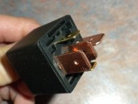
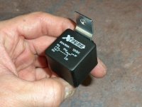
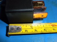
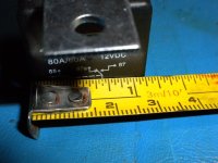
PS: I am looking for relays ( I will beef them up ) for use with 9C hubs (I have many) but I have 2 builds in desperate need of the proper relays... they will both be running 63v and maximum of 60A Primary Current with Infineon 9FET. If anyone has spare (bought in bulk and willing to sell / ship to Philadelphia area) I would love to buy a batch that is known to work. I am not above beefing up the relays with solder wick (love the stuff) to improve current handling... I expect a max systained between 50-60 amps continuous... any reasonable offer won't be turned down, I have some relays on order but I'd love to work with a known working combination.
Thanks for all the info guys!
-Mike

") . doc its just what your looking for if you want that speed record. i got 54mph and it was only a block :wink:
. doc its just what your looking for if you want that speed record. i got 54mph and it was only a block :wink: