BlackArrow said:
Hi Guys,
Doc said that is 5303/5306 mods not 5304/5308 but my motor is X5304

and see allot of potentionel for a electric dirt bike in the future with this 5303/5306 setup. :wink:
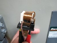
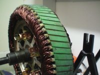
Doc did you have cut a little bit the stator with your Dremell to fit the relay like it's seems on the picture ?
Good day!
Black Arrow
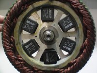
Yes i had to cut the stator aluminum armature.. but it will not affect the structure stability.
now i'm desining
a PCB to hold and solder and link every relay tabs in serie parallel connection.. no teflon wire .. just big beffy trace!!
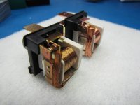
Less risk of melting wire skin, and the relay tab structure will stay in place in case where overtemp could occur.. remember i tested these relay to up to 140 celsius and the only thing i noted i sthat the tab just oxydise a bit but the plastic structure of the relay stay in place...
Here is a picture i did to help me finding out the relay tab holes on the PCM:
( Now i'm wondering if i connect al 6 relay coil in serie to get 72V needed at low current or if i connect all them in parallel for 12V needed and high current demand from the coil...
I guess that serie is better cause all coil would have the exact same current and probably will energize all at the same time making the 6 contacts synchronization better, and also helping in case where one relay would malfunction.. all other would cut and avoiding erratic combinaison of relay ON and OFF making a big BOOM on the controller with some smoke!...
Doc