Electrical question about my 1983 GS450L budget screamer.

Joined
Apr 10, 2023
Messages
11
Location
Trenton, Ontario
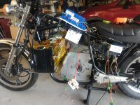
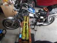
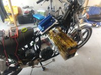
Good day everyone. I am building an E Motorcycle from an old 1983 Suzuki GS450L. The core of the project is this kit: Home :: Motorcycle & Kart Kits :: Budget Screamer (28KW, 72V Brushed). I am using 2 hybrid bus BAE batteries in series to make 80V. The project has been rideable since last summer but it's not polished enough to be inspected and insured yet. The motorcycle rides quite nicely!
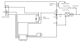
I am using a DC to DC converter to get 12V power for all the basic chassis electrical services. There is no 12V battery at this time, although that could change if required by local laws.
My only question is: The DC-DC converter uses a common negative (ground) for the 12V and 80V circuits. I decided to wire it to the negative terminal of the 80V battery, after the BMS. It seems to work ok but I could swear it changed the behaviour of the motor when throttle is chopped. It now seems to give a little kick before powering off. Any ideas why that would be? I'm not in love with this common ground idea because I was hoping to keep the two systems separate.

Thanks in advance.
 

Attachments

  • IMG_20220716_121921014.jpg
    IMG_20220716_121921014.jpg
    4 MB · Views: 34
  • IMG_20220701_162120528.jpg
    IMG_20220701_162120528.jpg
    3.9 MB · Views: 33
  • IMG_20220716_121903301 (1).jpg
    IMG_20220716_121903301 (1).jpg
    4 MB · Views: 33
My only question is: The DC-DC converter uses a common negative (ground) for the 12V and 80V circuits. I decided to wire it to the negative terminal of the 80V battery, after the BMS. It seems to work ok but I could swear it changed the behaviour of the motor when throttle is chopped. It now seems to give a little kick before powering off. Any ideas why that would be? I'm not in love with this common ground idea because I was hoping to keep the two systems separate.

You can get isolated DC-DC converters; they will have at least four wires (two in, two out), where the non-isolated may only have three (just one ground wire). Four wires isn't a guarantee of isolation, of course--you can check using a multimeter on continuity or ohms between the input negative and output negative (grounds) and should not get any reading between them. If you get a low ohms reading it is not isolated and would just be like your present DC-DC.


For the behavior change, some thoughts:

If the DC-DC is not powering anything connected to the controller (just things like lights, horns, etc), it shouldn't affect the controller's operation, unless it is so badly designed that it creates feedback noise on it's output back to the battery and that gets to the controller (which would also have to be badly designed to allow that kind of noise to get past it's filtering to cause problems).

If it is powering something the controller connects to, then noise from the DC-DC's output could affect things (but it also wouldn't matter if it was isolated if it's feeding the controller anyway, it would require a common ground).

Do you have a complete wiring diagram of how you *actually* have it wired that you can post? (not just whatever diagram the system came with, if any, but tracing out your wiring and drawing it out, becuase sometimes this is different for various reasons).
 
My question is, how is that super long battery fitting in your frame?!?
Fair question! I fabricated a support structure and a case to hold them. It is roughly the same width as my VStrom 650 but given the small frame of this bike, it looks ginormous. The weight is well balanced and there is no chance of it contacting the ground unless I drop it. Those BAE batteries are so well made, it seemed like a shame to destroy them... Kind of gives the bike a boxer engine look, I guess?
 
You can get isolated DC-DC converters; they will have at least four wires (two in, two out), where the non-isolated may only have three (just one ground wire). Four wires isn't a guarantee of isolation, of course--you can check using a multimeter on continuity or ohms between the input negative and output negative (grounds) and should not get any reading between them. If you get a low ohms reading it is not isolated and would just be like your present DC-DC.


For the behavior change, some thoughts:

If the DC-DC is not powering anything connected to the controller (just things like lights, horns, etc), it shouldn't affect the controller's operation, unless it is so badly designed that it creates feedback noise on it's output back to the battery and that gets to the controller (which would also have to be badly designed to allow that kind of noise to get past it's filtering to cause problems).

If it is powering something the controller connects to, then noise from the DC-DC's output could affect things (but it also wouldn't matter if it was isolated if it's feeding the controller anyway, it would require a common ground).

Do you have a complete wiring diagram of how you *actually* have it wired that you can post? (not just whatever diagram the system came with, if any, but tracing out your wiring and drawing it out, because sometimes this is different for various reasons).
So, I finished the schematic. You will see that the DC/DC converter is grounded to the 80 V battery but not the frame. Should I also run a wire to the frame? I tried it like this and it worked but I am not sure what path the 12V system takes to ground. Probably the converter case, I suppose.

Thanks for the help!
 

Attachments

  • circuit.png
    circuit.png
    21.8 KB · Views: 6
Fair question! I fabricated a support structure and a case to hold them.
Wait, I thought you were just doing that for testing or something. I would say you most definitely need to change that battery configuration. This is dangerous in so many ways. It’s best to keep the battery contained within the frame in case you hit something or lay the bike down.

Are those cells lithium ion? I tried looking it up.
 
Are those cells lithium ion? I tried looking it up.
look like A123 ANR26650M1B so lithium ion LiFePO4 but agree with containing the battery pack within the frame. perhaps these 40V BAE LFP
 
look like A123 ANR26650M1B so lithium ion LiFePO4 but agree with containing the battery pack within the frame. perhaps these 40V BAE LFP
You are correct, these are precisely the packs in question. The battery box is made of 10mm thick ABS with alu end caps. The support structure is made of 25mm alu tubing and designed to deform until extreme load, allowing the whole pack to shift away from an impact. It's quite sturdy, actually, while allowing for the case to move instead of fail. The long term goal is definitely to build custom packs that will fit within the frame eventually. This is proof of concept. The battery packs are roughly 70% capacity as is.
 
Last edited:
Wait, I thought you were just doing that for testing or something. I would say you most definitely need to change that battery configuration. This is dangerous in so many ways. It’s best to keep the battery contained within the frame in case you hit something or lay the bike down.

Are those cells lithium ion? I tried looking it up.
That will change eventually, yes. I'm not comfortable with it as is. Works though!
 
So, I finished the schematic. You will see that the DC/DC converter is grounded to the 80 V battery but not the frame. Should I also run a wire to the frame? I tried it like this and it worked but I am not sure what path the 12V system takes to ground. Probably the converter case, I suppose.

The casing could be grounded; you have to test to find this out (similar to the way you can test for isolation).

For future reference, if you don't know whether a connection (required or undesired) exists, you must test for it and either make it or remove it, to correct or prevent problems. ;)

For grounds, normally you want to pick a single ground point and run all grounds to that point. If you have multiple ground points you can end up with ground loops where some voltages are "lifted" above what they should be by induced currents in the grounds, etc. If there is only one ground reference point, then they all would work the same way, and interference that causes undesired operation is minimized.

I'll look at the diagram and see if there's anything else that might cause such problems.
Thanks you very much. I love science experiments!
 
Back
Top