• Hello ES! We could use some help to get us past the finish line on building the new knowledgebase for the forum.
    Can you donate? Please see our fundraising page. Thank you!

ES PAS experts

E-HP

Super legend
Joined
Nov 1, 2018
Messages
10,166
Location
USA
I'm looking for some links to good guides/articles or threads for PAS (cadence) setup and troubleshooting. I'm going to add it to my FAQ so the link will be easy me to grab in the future. I'm looking for something like TommyCat's bldc motor testing/troubleshooting guide or his hall throttle guide, but helpful threads would also work. I'm not looking for manufacturer specific guidelines, although I have some links to things like Grins's PAS unit, since it takes an oddball voltage other than 5v, or their use of the PAS sensor for backwards pedaling/breaking and a link to one of docw009 threads for KT controllers and the setup, that I'll add to my FAQ PAS the entry. If the links are part of a bigger thread, I plan to link to the relevant post. I'd also like to include something on default PAS assistance levels when running without a display, and other special cases.
Thanks ahead of time for your input. I know there's a lot of threads out there, but if you've seen one that's comprehensive and checks all of the boxes, that would be great.
 
There are quite a few ways PAS can work. I've got posts with details on some of the ones I've run across or read of in various threads, scattered around the forum; not sure the best way to find them in a search though, so a summary from memory (verify these as they may be wrong or incomplete):

First you have the actual PAS type.

There is cadence, and torque.

Most torque sensors also have a cadence sensor. Some of these are independent outputs, analog for the TS and time pulses for the CS. Some of these are entirely digital, as serial data streams, like the various Canbus types (bafang), or the custom data formats some companies may use.

Cadence-only sensors are usually digital, but not often as serial data streams.

There are multiple types of cadence sensor, which may also apply to the ones integrated iwth TS.

Grin's PAS page has more detailed info, but generally there are types that:
-- simply output a pulse whenever a magnet passes.
--latch to a state when a magnet passes, and unlatch when the next one passes.
--output a pulse whenever a magnet passes *in the correct direction* and no output in the other
--output what amounts to a PWM signal based on the cadence
--output a quadrature signal that encodes both speed and direction (these have two signal wires instead of one)
--most operate from 5v, but some require other voltages.
--some output a standard 0-+V range, some have open-collector output that grounds when active and reuqire a controler-side pullup resistor to +V to complete the signal with an off state (like a typical UVW/ABC motor hall)


Torque sensors vary quite a lot in their design, construction, operation, and output type and range.
--They may output a simple analog voltage range, but even this varies.
--some output a range similar to a throttle, and could, with proper safety features in the system, be connected in place of a throttle.
--some output a range starting around halfway up the voltage range, decreasing or increasing in voltage with applied torque.
--They may require a single voltage to operate, or multiple, and that may be 5v, 10v, or some other voltage.
--scale and voltage range vs torque input varies such that you'd have to refer to the manual for the specific sensor on that.
--some use serial data outputs and are probably only compatibel with the systems they come with


Controllers vary widely in how they implement PAS.
--most only use it as an on/off engage switch (are you pedalling, or not) to activate the assist at whatever the presently-chosen assist level is on the display.
--some may actually read the cadence and provide proportional assist (like the Cycle Analyst can do)
--some may not provide PAS assist except at specific assist levels chosen on the display. When a display is not present they may not respond to PAS at all, or respond only at an unchangeable default level.
--TS-based systems may use a combination of cadence and torque to determine assist amount, or levels in the display, or both, or may ignore the cadence and only use that to be sure you are actaully pedalling and not just resting your feet on the pedals causing a false torque reading.


There's a lot of other possible detail to how they can work....


To troubleshoot many PAS related issues, you have to know how your system is intended to respond to it, and which type of PAS it uses, etc.

others can be tested just like throttles or motor halls.
 
There are quite a few ways PAS can work. I've got posts with details on some of the ones I've run across or read of in various threads, scattered around the forum;
Thanks! You’ve provided enough details to reference this thread in th FAQ. I guess for the troubleshooting, how to do the connections to have it operate is one aspect, while getting it to work with the controller and ultimately spin the motor is another. The latter may involve physical testing as well as parameter setup. Another aspect, when replacing a unit, would be how to determine what type of replacement to use/purchase, given the physical characteristics and functionality of the existing unit.
 
I'm looking for some links to good guides/articles or threads for PAS (cadence) setup and troubleshooting.
Justin has an article about PAS sensors:
 
Thanks! You’ve provided enough details to reference this thread in th FAQ. I guess for the troubleshooting, how to do the connections to have it operate is one aspect, while getting it to work with the controller and ultimately spin the motor is another. The latter may involve physical testing as well as parameter setup. Another aspect, when replacing a unit, would be how to determine what type of replacement to use/purchase, given the physical characteristics and functionality of the existing unit.
Yes, the troubleshooting steps of a PAS issue will depend partly on the kind of PAS, how it's setup, how it works in that system, etc. That's why I typed up what I could from memory of that stuff; making a good troubleshooting flowchart / document depends on much of this info.

Determining which steps to follow, for a user doing this TSing, will probably be difficult unless the document explains how to tell....

I'd try writing one but I'm not really able to focus well enough right now; maybe at some point, but I wouldn't recommend waiting for me. :/

Justin has an article about PAS sensors:
Yes; it's referenced/linked in the text of my post (but it doesnt' show the page preview because I added it just as highlighted text, so I guess it isn't very visible; sorry).
 
while getting it to work with the controller and ultimately spin the motor is another.

One issue I am aware: KT controllers are often reported to have difficulty working with 12 pole PAS. But to be sure, someone who has worked on that setup should confirm.
 
Yes, that's another detail I forgot in my list:

--different cadence sensors have different numbers of magnets (poles), and different orientations of those magnets.

--different controllers have different limits to the number of poles of the cadence PAS sensor. (there's always a limit even if it isn't expressly stated or set anywhere)

This means that magnet rings from one system may not work on another, even if the cadence sensor itself does.

Some CS have the magnet ring integrated, so it's usually a whole unit that requires removing the crank from that side to slide it over the BB crankshaft.

Most have the MR separate. Some of these use a split ring that can be installed on the BBCS without removing the crank, but most still require the crank to be removed.


If using a directional sensor that has the magnets polarized in a specific way or patterhn, installing the ring correctly is important, and it's then a 25% (or less) chance of getting it right if not following instructions or those instructions are poor (or wrong themselves). The ring can be installed two ways, and the sensor itself can often be installed two ways, *and* it's usually possible to install these on either side of the BB shell, even though some of them will only work if they're installed on the correct side of the BB shell because of the orientations required for the sensor and magnet ring.

So...you also have to know whcih of all the above you have in a system to figure out why it might not be working, and know which things to check.
 
number of poles of the cadence PAS sensor.
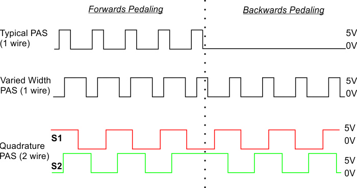
It's not just the number of poles, but the duty cycle of the signal, that carries the rotation direction information.
Most cheap 3 wire PAS are working with the "varied width" principle.
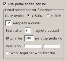
The controller expects a certain range for the duty cycle to start the motor. Kunteng has some parameters to tune the controller to the PAS signal, but knowbody knows, how that is working exactly.
Lishui has more details to tune the controller to the PAS waveform.

1752126288587.png
PAS_Signal_Levels.jpg
 
It's not just the number of poles, but the duty cycle of the signal, that carries the rotation direction information.
Most cheap 3 wire PAS are working with the "varied width" principle.
The controller expects a certain range for the duty cycle to start the motor. Kunteng has some parameters to tune the controller to the PAS signal, but knowbody knows, how that is working exactly.
Lishui has more details to tune the controller to the PAS waveform.

Almost all of the 3 wire PAS I have come across provides pulses only in one direction (checked in scope), their duty cycle being far away from 50%.

But I am on the other side of the sphere (globe), perhaps the reason for the above type being common.

Does the PAS's that work with KT & Lishui provide pulses in both direction?
 
Back
Top