EU type 2 connector "slow" dc charging

sss

10 mW
Joined
May 21, 2015
Messages
20
hello guys .
i want to connect my car (not DIY EV) to a small solar array i have .
i have custom solar inverter which first boosts the 48v battery voltage to 400V DC and than converts to 220v AC (dual stage inverter DC-DC-AC)

i wonder if i can connect the car directly to 400V DC bypassing the AC inverter , as described here Type 2 connector - Wikipedia under "pins" , you can see that L2 and L3 phase pins can accept DC voltage (low and mid DC) , also wonder if the standard current control with PWM duty cycle on CP also applied to DC .

would like to hear if anybody has any experience with it .
thanks
 
What are the voltage / current limits for your specific car's inputs?

What are the current output limits for your solar 400VDC output? How does it limit this current? (hiccup mode, where it shuts off when current is exceeded, or CC mode where it lowers the voltage to maintain that max current, or something else?)
 
i wonder if i can connect the car directly to 400V DC bypassing the AC inverter , as described here Type 2 connector - Wikipedia under "pins" , you can see that L2 and L3 phase pins can accept DC voltage (low and mid DC) , also wonder if the standard current control with PWM duty cycle on CP also applied to DC .
You can do it but it is not easy.

You have to control both current and voltage; voltage control alone is insufficient. Different chargers use different standards. The new NACS standard uses PLC (powerline communication, a conducted RF scheme) over the CP pin. The CHAdeMO standard uses CAN. You also have to do an insulation test before charging starts - usually it's a phase where the charger raises the input voltage to 500VDC and monitors leakage before the contactors are closed.

The controller is generally very finicky about what has to happen before it will close its internal battery contactors, because at that point the battery is connected directly to the charge port without much protection.

There are now a few companies selling fast chargers that connect to 480VAC. There is one that uses a three-port DC/DC (one for battery, one for solar, one for car charging) specifically for off-grid charging systems. I forget the name of the company; I see them at every solar trade show.
i'm looking into it just to bypass the inverter for slightly better conversion efficiency , not a big deal .
i know the standard ccs2 hand shake protocol is pretty simple with cp , pp pins when charging with AC .
i also heard that for high power DC (the lower 2 large pins of the ccs2 connector) the hand shake is totally different and higher level of communication is used , like CAN .
but i didn't knew i can run DC through the L2 and L3 phase connectors , so i wonder if those 2 use the "simple" or advanced communication protocol .

i'm not even sure if the car actually cares if i supply it with 220v AC or DC through the regular L1 and N , the voltage is limited at 500V , and i'm sure the first thing the onboard charger does is rectifying that AC voltage to DC anyways .
there is even cooler option listed there (see my attachment) where you can combine 1 phase ac with dc . so in theory i can connect the car to the grid , and add dc from solar , but there is no explanation of this configuration anywhere , for example how can i current limit each one separately .
 

Attachments

  • cap1.JPG
    cap1.JPG
    25.3 KB · Views: 1
What are the voltage / current limits for your specific car's inputs?

What are the current output limits for your solar 400VDC output? How does it limit this current? (hiccup mode, where it shuts off when current is exceeded, or CC mode where it lowers the voltage to maintain that max current, or something else?)
my car can charge at up to 100kw when connected to high power dc (not the connector i intend to use)
standard single phase is limited to 70a i think , and 3phase is 63a per phase .
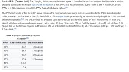
my solar array is not large , max 16a , i'm planning to limit the current via the car's evse signalling protocol , where you send 1khz square wave that sets the current limit depending on duty cycle .see attachment.
 

Attachments

  • cap2.JPG
    cap2.JPG
    136.9 KB · Views: 0
my car can charge at up to 100kw when connected to high power dc (not the connector i intend to use)
standard single phase is limited to 70a i think , and 3phase is 63a per phase .
my solar array is not large , max 16a , i'm planning to limit the current via the car's evse signalling protocol , where you send 1khz square wave that sets the current limit depending on duty cycle .see attachment.
Wattage isn't relevant to the questions asked in my post.


I asked specifically about voltage and current because you must know:

-- that the specific input you are using can handle the voltage output by the source, without damage, and that it doesn't require a higher voltage,

-- that the current draw asked for by the input you are using doesn't exceed what the source can output *at the voltage you require*.

You must also know that your source can limit current in a useful way for battery charging, via CC mode where it drops the voltage to meet current demand. If it drops the voltage in hiccup mode where it simply shuts off the output upon overcurrent, it's not useful for charging.


Phases imply AC charging inputs. Those imply an input that is designed for AC source, and how they will behave with a DC input would either require testing (potentially destroying them if they can't handle this) or reverse-engineering them to determine if they can actually use a DC source safely.

Not every AC-powered device can be powered from DC.
Agreed. I can think of several ways to design a power factor corrected AC to DC that would either not work or be destroyed if you tried to run it on DC. Many DO work that way (most of the Meanwells for example) but that doesn't mean all or even most will.
 
Agreed. I can think of several ways to design a power factor corrected AC to DC that would either not work or be destroyed if you tried to run it on DC. Many DO work that way (most of the Meanwells for example) but that doesn't mean all or even most will.
it's irrelevant for this topic . check the link i provided in the first post , you can clearly see that "slow dc charging" can be connected to phase 2 and phase 3 inputs on the type 2 connector .
 
it's irrelevant for this topic . check the link i provided in the first post , you can clearly see that "slow dc charging" can be connected to phase 2 and phase 3 inputs on the type 2 connector .
Does your car support that?
 
Does your car support that?
i dont know . i never seen this implemented on any car yet . i know my car onboard charger is 22kw and can support 3phase 400v ac .standard rapid charging is done via ccs2 connector up to 100kw
 
Last edited:
i dont know . i never seen this implemented on any car yet . i know my car onboard charger is 22kw and can support 3phase 400v ac .
I have never seen any charger that supports DC charging on any pins other than the Combo pins. Nor have I ever seen any car that uses this feature.

I strongly suspect that this feature is like the Status D state on the Control Pilot in the J1772 standard. It's in the spec but no one ever uses it or supports it.
 
When I finish converting the CRX to electric, it will have a 355 V nominal battery. Likewise, my home storage battery and hybrid inverter might get an upgrade to a HV system, roughly the same voltage. I might try and devise a sneaky DC port for V2G which can supplement the house battery. Take it from 12 kWh to 36 kWh. Might have some inrush current though :)
 
Back
Top