PJD said:
Gary or Richard,
This is a bit of a minor thing, but in my old versions (and presumably this version too) the shunt indicator LED's get awful bright, which in conjunction with the flickering, strobe-like in unison, can be vertigo/headache inducing. (Both me and my wife experience this). Someone with epilepsy could have trouble with it.

Can the brightness be reduced with a change in resistor(s) value - or an alternate LED used?
Thanks!
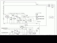
Hmm, I haven't seen that. I think it is somewhat cell-dependent, and/or relative balance-related. All I've seen is that the LEDs, when they first come on, start out bright, but dim down after a bit. Near as I can tell, when the LEDs are bright, the shunt for that channel is in full bypass mode, which means the cell is about as full as it is going to get. The reason they dim is I think because the charger/supply's CV limit is being hit, so the total current is being reduced. That tells me the cells are not only full, but fairly well balanced as well. In any case, when a cell's LED first cmes on, the transistor and shunt resistor are already in the bypass mode and the cell is close to being full (95%?). When the LED is on bright, the cell is in full bypass, which means the cell is as full as it is going to get. Left unchecked, the shunt circuit would oerload and get swamped. A bit after the LED is on brightly, and the shunt is in full bypass, about to be overloaded, the opto for that channel turns on, which causes the ANY SHUNT ACTIVE to turn on, which causes the gate driver to turn off the FET. With the current temporarily removed, the voltage at the cell will drop a bit, which cause the opto for that channel to go off, which causes the FET to turn back on. This oscillation, or "throttling" is what causes the shunts to keep from being overloaded/swamped, and is what causes the "flicker" you are seeing.
Before this latest change, once the last LED came on and got bright, it would eventually go dim as well. All I would do, though, is wait for the last one to come fully on, and then I disconnected the charger. With this new logic, once the last opto trips, which means the LED is fully on and the cell is full, the ALL SHUNTS ACTIVE signal is tripped, which causes the SCR to fire and the FET to be turned off, and kept off, until power is cycled and the circuit resets.
The main LED has two colors, red and green. These are driven by the complementary outputs of the gate driver. When the FET is on, the LED is red. When the FET is off, the LED is green. Durring the CC phase, the FET is always on, so the LED is red. When the optos start tripping, the duty cycle of the FET gradually changes from on mostly, to 50-50, to off mostly, so the LED color gradually shifts from red, to redish-orange, to orangish-yellow, to a yellowish green. Once the SCR trips, the color snaps to solid green.


