GGoodrum
1 MW
Those cells are the standard PSI LiFePO4 variety, so yes, the BMS will work fine.
With all of these LiFePO4-based cells, but particularly the a123s, what you are trying to prevent is letting the cell discharge past the "safe" point of around 2.0V per cell. It has been my experience with a123 cells that if they are discharged to the point that the "resting" voltage is between 1.0V and 1.5V, the cell will have been stressed, and its capacity will be reduced about 10%. Below 1.0V, or thereabouts, and the cell is toast. This is really easy to do with a123 cells, especially if you have multiple cells in parallel, to boost the capacity. This also boosts the "C" rating, which is already at least 30C continuous. What happens is that there is very little voltage sag, under load, and it remains fairly constant all the way up until the end, when the voltage dumps quick (literally seconds...). You just have no notice that you are running out of "juice". With SLAs, and other chemistries, you usually can "feel" the performance drop as you use the pack. With paralleled a123s, the power feels the same at the beginning of the capacity as it does 10 seconds before it dumps.
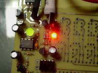
What the LVC needs to do is cut off the load as soon as it detects that any cell/cell block, has begun this "spiral of death". It happens so quick that whether the vlue is 2.1V, 2.5V of 2.7V doesn't really matter. If you cut the load as soon as this happens, the resting voltage of the cell is still going to be at, or over 3.0V. When I did the first LVC boards for my a123-based packs, I used the 2.7V version of the TC54s. When I used these with the LiFeBatt (PSI...) cells, however, I found under heavy loads, the LVC was kicking in too soon, so I used the 2.1V parts for the LiFeBatt packs. Later, I tried the 2.1V version on the a123 packs and couldn't see a difference, so now I just use the 2.1V parts for everything.
-- Gary


