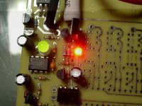
Even Newer 4 to 24-cell Battery Management System (BMS)

Those cells are the standard PSI LiFePO4 variety, so yes, the BMS will work fine.

With all of these LiFePO4-based cells, but particularly the a123s, what you are trying to prevent is letting the cell discharge past the "safe" point of around 2.0V per cell. It has been my experience with a123 cells that if they are discharged to the point that the "resting" voltage is between 1.0V and 1.5V, the cell will have been stressed, and its capacity will be reduced about 10%. Below 1.0V, or thereabouts, and the cell is toast. This is really easy to do with a123 cells, especially if you have multiple cells in parallel, to boost the capacity. This also boosts the "C" rating, which is already at least 30C continuous. What happens is that there is very little voltage sag, under load, and it remains fairly constant all the way up until the end, when the voltage dumps quick (literally seconds...). You just have no notice that you are running out of "juice". With SLAs, and other chemistries, you usually can "feel" the performance drop as you use the pack. With paralleled a123s, the power feels the same at the beginning of the capacity as it does 10 seconds before it dumps.

What the LVC needs to do is cut off the load as soon as it detects that any cell/cell block, has begun this "spiral of death". It happens so quick that whether the vlue is 2.1V, 2.5V of 2.7V doesn't really matter. If you cut the load as soon as this happens, the resting voltage of the cell is still going to be at, or over 3.0V. When I did the first LVC boards for my a123-based packs, I used the 2.7V version of the TC54s. When I used these with the LiFeBatt (PSI...) cells, however, I found under heavy loads, the LVC was kicking in too soon, so I used the 2.1V parts for the LiFeBatt packs. Later, I tried the 2.1V version on the a123 packs and couldn't see a difference, so now I just use the 2.1V parts for everything.

-- Gary
 
when you make the lvc only boards and the next gen of bms you may want to add a latching system or a capacitor to the lvc optos so once the lvc hits it stays off until the power is cycled or a reset button is pushed because.

what will happen is when the lvc comes on then it is the same as hitting the brakes triggering the brake inhibit and then as soon as the load is released the voltage comes back up and the lvc is let off and the load returns back and it is like pulsing the brakes causing a jerky operation.

as of the power drop i would think performance would drop because (correct me if i am wrong) lifepo4 is like nicad's and nimh in their discharge curve and if you ever used a walkman or portable tape player with nicads or nimh batteries when they go down the tape slows down very quickly (something like from the simpsons eposide where homer,bart and milhouse are on the ocean in an inflatable raft on the episode with the pocket knife.

according to my calculations 2.1 volts times 16 cells is about 33.6 volts witch for the crystalyte 4840 controller and phoenix brute would notice very little power.

i know this because i bypassed the lvc so i could see if 24 volts could run it and it barely had power to move on flat surface.


GGoodrum said:
Those cells are the standard PSI LiFePO4 variety, so yes, the BMS will work fine.

With all of these LiFePO4-based cells, but particularly the a123s, what you are trying to prevent is letting the cell discharge past the "safe" point of around 2.0V per cell. It has been my experience with a123 cells that if they are discharged to the point that the "resting" voltage is between 1.0V and 1.5V, the cell will have been stressed, and its capacity will be reduced about 10%. Below 1.0V, or thereabouts, and the cell is toast. This is really easy to do with a123 cells, especially if you have multiple cells in parallel, to boost the capacity. This also boosts the "C" rating, which is already at least 30C continuous. What happens is that there is very little voltage sag, under load, and it remains fairly constant all the way up until the end, when the voltage dumps quick (literally seconds...). You just have no notice that you are running out of "juice". With SLAs, and other chemistries, you usually can "feel" the performance drop as you use the pack. With paralleled a123s, the power feels the same at the beginning of the capacity as it does 10 seconds before it dumps.

What the LVC needs to do is cut off the load as soon as it detects that any cell/cell block, has begun this "spiral of death". It happens so quick that whether the vlue is 2.1V, 2.5V of 2.7V doesn't really matter. If you cut the load as soon as this happens, the resting voltage of the cell is still going to be at, or over 3.0V. When I did the first LVC boards for my a123-based packs, I used the 2.7V version of the TC54s. When I used these with the LiFeBatt (PSI...) cells, however, I found under heavy loads, the LVC was kicking in too soon, so I used the 2.1V parts for the LiFeBatt packs. Later, I tried the 2.1V version on the a123 packs and couldn't see a difference, so now I just use the 2.1V parts for everything.

-- Gary
 
Actually, the way it works is that let's say you are near the end of the capacity, and you are going up a hill, so the throtle is wide-open. What will happen is that one, or more, LCV channels will trip, which causes the controller to kill the throttle. The voltage recovers very quickly (less than a second...) so the throttle signal is back to full-on. What you feel is a 'hit", not unlike a big tuna hitting while sportfishing. If you stay on the throttle, it will hit again. What I've found with my LiFeBatt-based packs is that when this first full-throttle "hit" occurs, there is about 10% capacity left, and if I back off the throttle, I can go about another mile, or two, before it starts "hitting" with even the slightest throttle. At that point, my WattsUp says I'm right at the end of the full capacity. With the a123 packs, which have much less voltage sag, once it hits the first time, you really don't have much left, maybe 5%, if that.

In any case, the oscillation is actually a desirable trait, in my opinion, so I'm not too interested in adding any sort of latch that has to be reset. That would be a pain.

One other thing you aren't getting is that with different chemistries, there are larger differences of the voltage under load at the beginning of the capacity than than near the end. SLAs, for instance, are usually the worst case, with a very noticible difference in performance as the capacity is used up. The higher the "C" rating, the smaller the difference you will see/feel between the beginning and the end. With multiple a123 cells in parallel, the differences are very small, even with 50A loads. The point is that the cells don't gradually start reducing their voltage down, until they get to 2.1V. What happens is that the power "feels" the same, all the way until the end, and then it is like a breaker tripped, or a plug came undone. You just don't "notice" that you are at the end of the capacity. the whole reason I did the LVC board in the first place is because I killed a bunch of cells, over-discharging them. I use to have four 16s1p a123 packs on one of my bikes. I had these connected in parallel at the pack level. One time, I inadvertantly forgot to connect two of the four packs, and then went out on one of my "normal" rides. A little over halfway through, I suddenly lost all power. It was fine one second, and then dead the next. I seriously thought the controller had blown. It was then I noticed that only half the packs were connected. The power felt no different with 2 or 4 of the 16s a123 packs in parallel. I then swapped in the "good" packs, and went home. Later it turned out in one pack there was one cell that was completely dead, and three more that ended up being "stressed". The second pack had two dead cells and two that were stressed. Anyway, I never noticed a drop in power, and the controller's LVC circuit never was tripped.

Because this "dumping" happens so quickly, you really need to do the LVC function at the cell level. You can have one cell at the point it is being damaged, and the rest of the cells keeping the total pack voltage well above the controller's LV cutoff point. Even with healthy, well-balanced cells, they are never going to be perfectly in sync, when it comes to exact capacity levels.

-- Gary
 
CamLight wrote:
"Not a great solution but I've used zero-ohm 1/8W through-hole resistors as jumpers. Just solder the lead ends down onto small bare pads. The resistor body holds everything a bit off the PCB."

That's a good solution where you are using a through-hole resistor anyway, just solder in the jumper or the resistor. But once you get used to SMT boards with fine pitch components and 0805 or smaller resistors, the two holes for the jumper just look HUGE on the board, and the jumper length is longer than your whole circuit. Not so neat.

I find that when doing two-layer analog SMT boards I can usually lay out almost all the signal traces on the component (top) layer. That leaves the bottom for power traces and a ground plane, which is a good thing. (If the board is too dense to do that, I usually go to four layers. Ground planes are very important for good EMI performance, which is critical in vehicle applications, be they spark ignition or EV.)

The only bad thing about Richard's jumper hole is that you need two holes, to go down and then back up, and they take up real estate on both sides of the board. But you could choose to put the two very close together so they don't interrupt the ground plane. And you could use much smaller holes -- a resistor lead wants an 0.035 hole with maybe 0.055 solder pad, where I usually use a .020 hole and .028 pad for a via that doesn't need anything soldered to it. The pads for the zero ohm resistor take up almost 4x the board area compared to the two vias.
 
when a cell dies because of over discharging or over charging what happens when you try to charge the dead cell?

refuses to take a charge?

takes a charge but does not hold the charge?

shorts putting a higher voltage across the pack cooking the remaining cells?


opens up so no power can go through causing a condition like a pack that is not connected or a cell tab broke off?
 
4.2V HVC
3.0V LVC
1A Shunt
Lipo BMS works GREAT!!!


Here is a closeup of the 3.9ohm resistor and 1.5A BJT. Note how thick the legs are. . . I had to end up trimming the legs down to nubs then carefully soldering them in like surface mount parts. The end product is quite strong due to the thickness of the legs. I feel confident about it.

View attachment BMS_011.jpg

I populated the control circuit and only the very first channel.
I applied a 4S pack to the regulator and shorted the grounds together

First thing I tested the LVC.
I applied 3.40V to the first battery port and started to turn it down
Works like a charm right at 3.0V
It has 100mV of hysteresis so turning the voltage back up to slightly over 3.10V kicks the brake off.
This will be perfect.

View attachment 4

I then applied 4.1V with a power supply through a Watts up into the first battery port.
When I roll the voltage up to 4.2V the LED ramps up very quickly and I get 1A across the 3.9ohm shunt resistor.
This is an easy way to test since you dont even need the 12V supply

View attachment BMS_002.jpg
View attachment BMS_006.jpg

When I go just a touch higher the green light pops on.

BMS_007.jpg

If I roll the voltage back down the green light stays on.
Excellent!

Nice work guys. I was a little worried that changing the HVC voltage divider, Shunt resistor, and Shunt BJT would give me enough cumulative error to send me into the weeds but not so! Works exactly as advertised / calculated.


My "Completely Autonomous Three Dimensional Maze Solving Robot" give you a Borat High Five!

Robot%20on%20floor.JPG


-methods
 
ejonesss said:
when a cell dies because of over discharging or over charging what happens when you try to charge the dead cell?

refuses to take a charge?

takes a charge but does not hold the charge?

shorts putting a higher voltage across the pack cooking the remaining cells?


opens up so no power can go through causing a condition like a pack that is not connected or a cell tab broke off?

What happens is that the cell just gets hot, and doesn't take the charge.
 
Methods --

That's great to know that the 1A mod works. What is the shunt transistor part number you used? Maybe in this next version we can make it easier to use these. How many watts are the 3.9ohm shunt resistors rated for?

-- Gary
 
(1.5A BJT)
512-BD14016STU

But mind you that was not really carefully selected. Fechter just pulled that out of a hat as a reasonable replacement. To really make it work the holes in the board would have to be just a touch larger.

The 3.9ohm resistors are rated at 5W and I am running them at 4.5W which is near the hairy edge. You know how it goes with these things though. . . So long as I dont beat the tar out of it they will be fine. I doubt that this circuit will be on for more than a few minutes on any given charge. We will see if the BJT needs a heat sink, I dont think it will.

Before I **REALLY** say it works allow me to burn it in real good.

I will set it up to burn 1A for 30 minutes then check the temps.
If they get out of hand I am thinking that a tiny little 12V fan will make this circuit run nice and cool.

-Patrick
 
methods said:
(1.5A BJT)
512-BD14016STU

But mind you that was not really carefully selected. Fechter just pulled that out of a hat as a reasonable replacement. To really make it work the holes in the board would have to be just a touch larger.

The 3.9ohm resistors are rated at 5W and I am running them at 4.5W which is near the hairy edge. You know how it goes with these things though. . . So long as I dont beat the tar out of it they will be fine. I doubt that this circuit will be on for more than a few minutes on any given charge. We will see if the BJT needs a heat sink, I dont think it will....


Cool. That definitely earns you a guinea pig award
Fried_guinea_pig2.jpg

I didn't check the lead diameter on those transistors. It would be easy in future versions to make the holes a bit bigger. The smaller transistors would still fit fine. It looks like the hole spacing is good.

The heat dissipation on the transistor may be on the hairy edge too, but they're rated for 150C. According to the datasheet, they can do 1.25 watts at 25C ambient with no heat sink. According to calculations, worst case dissipation with a 1 amp shunt will be around 1.1 watts. On a hot day or in an enclosure, they could get into overheat. A small fan would be an excellent way of preventing excessive temps on the parts.

If I was real clever, I could design a fan driver into the circuit that would only come on when it's needed. It would be simpler to run the fan from a separate supply. It may be possible to run a fan off the 12v control circuit supply, but the fan could not draw more than around 50ma @ 12v. This would also keep some juice flowing after the auto-cutoff, which may not be desirable.

The resistors can tolerate very high temperatures, so I wouldn't worry so much about them. I would worry more about them acting like little stove elements and cooking the parts near them. They could cook the circuit board material too. If they get really really hot, they can melt their solder, which is bad.

If your pack is reasonably balanced, the shunts should not stay on for very long anyway, but it is good to design for the worst case.
 
ErikK said:
The only bad thing about Richard's jumper hole is that you need two holes, to go down and then back up, and they take up real estate on both sides of the board. But you could choose to put the two very close together so they don't interrupt the ground plane. And you could use much smaller holes -- a resistor lead wants an 0.035 hole with maybe 0.055 solder pad, where I usually use a .020 hole and .028 pad for a via that doesn't need anything soldered to it. The pads for the zero ohm resistor take up almost 4x the board area compared to the two vias.

Yes, I was thinking of putting two very close together and using a very small size. It does suck up some real estate, but less than the other options, and it is cheap.
Another approach I thought of was to run a jumper trace on the top side and put a hole in the middle of the trace with no land. Then you can use the tip of a drill bit to make a divot in the trace, cutting it. It would be harder to reverse, but would take up a bit less space.

I hadn't considered maintaining much of a ground plane on the board but minimizing EMI is always good. I would be afraid of having a continuous ground plane for the whole board due to the voltage differences. Each cell circuit is independent and optically isolated, so a separate ground plane for each cell circuit should be adequate. If you want to be real anal, you could join the ground planes between cells circuits with capacitors.
 
For the through-hole version, I'm just placing the hole right in the middle of where the resistor will go, with one trace on the top, connectoing to one end of the resistor, and a second trace on the bottom, going to the other end of the resistor. If you aren't using the resistor, you do nothing. If the resistor is to be used, you drill the hole and then install the resistor. This takes up no more room than the resistor itself.

For the surface mount version, which I have no intention of doing any sort of hand installing, the 0 ohm part sounds like the easiest way to go.
 
GGoodrum said:
For the surface mount version, which I have no intention of doing any sort of hand installing, ....

Yes, for sure. I would envision installing all the resistors and letting the end user cut jumpers as needed for their application. I think the through hole will easier than zero ohm resistors.

Do they make surface mounted zero ohm resistors that are easy to snip?
 
fechter said:
If I was real clever, I could design a fan driver into the circuit that would . . .

Whoa whoa whoa. . . There are already so many part in that circuit that my hands are aching from all the soldering. . . and I only did the first channel :!: :mrgreen:

Thanks for the help fechter.

Here is a glass of milk and some toast for your contribution to Project Mayhem.
I wouldn't have gotten it right without your help.

milk.jpg
toast.jpg


-Patrick
 
instead of a zero ohm resistor wouldn't a piece of wire like one of the scrap leads from through hole mounted parts work?


fechter said:
GGoodrum said:
For the surface mount version, which I have no intention of doing any sort of hand installing, ....

Yes, for sure. I would envision installing all the resistors and letting the end user cut jumpers as needed for their application. I think the through hole will easier than zero ohm resistors.

Do they make surface mounted zero ohm resistors that are easy to snip?
 
ejonesss said:
instead of a zero ohm resistor wouldn't a piece of wire like one of the scrap leads from through hole mounted parts work?

Hmm... yes, but the idea is to use something that can be installed by automated assembly machines. I suppose there are some machines that could do it, but I don't think that's a standard feature for most. For a hand-built board it would be fine.
 
fechter said:
ejonesss said:
instead of a zero ohm resistor wouldn't a piece of wire like one of the scrap leads from through hole mounted parts work?

Hmm... yes, but the idea is to use something that can be installed by automated assembly machines. I suppose there are some machines that could do it, but I don't think that's a standard feature for most. For a hand-built board it would be fine.

Even for the hand-built, through-hole versions, the idea is to reduce the amount of labor involved, not increase it. Only a small number of people, actually, have requested a board for something other than LiFePO4, so I want the "extra" work to be tied to those versions. For LiFePO4, you don't drill the holes and you don't install the extra resistors.

-- Gary
 
I would be done except for the fact that "Quicksilver Radio Products" took their sweet frigging time shipping my 45A anderson connectors.
They left Oakland yesterday so I have my fingers crossed.

Here is the board minus power in and out.

-methods
 

Attachments

  • One step closer to hitting bottom.jpg
    67.3 KB · Views: 1,844
i used 2 pairs of 3 pin and 6 pin scooter throttle connectors from
http://www.electricscooterparts.com/wireconnectors.html

Item # CNX-40 and Item # CNX-53

since they do not make or sell both genders of standard balancing taps.

the 3 pin connectors connect up the pack + and - and center tap at the junction of cell 4 and 5.

methods said:
I would be done except for the fact that "Quicksilver Radio Products" took their sweet frigging time shipping my 45A anderson connectors.
They left Oakland yesterday so I have my fingers crossed.

Here is the board minus power in and out.

-methods
 
methods said:
I would be done except for the fact that "Quicksilver Radio Products" took their sweet frigging time shipping my 45A anderson connectors.
They left Oakland yesterday so I have my fingers crossed.

Here is the board minus power in and out.

-methods

Looks good, Patrick. I'm looking forward to hearing how it works at 1A of shunt current.

Also, did you say you were able to find the 3.0V through-hole (TO-92) version of the TC54 somewhere?
 
ejonesss said:
since they do not make or sell both genders of standard balancing taps.


They make them.
You just need to be clever.


View attachment Taps_001.jpg

You can get the straight though version but the 90 degree is MUCH better.
See how the two parts mate perfectly?


View attachment Taps_002.jpg
View attachment Taps_003.jpg

This provides strain relief and most importantly, allows you to solder without melting the case
When you try to solder the straight pin you will find that the pins melt out of the case too easy.


View attachment Taps_004.jpg

I sometimes cannibalize inexpensive "adapter" cables from places like Hobby City to make other types of balancing adapters.

-methods
 
GGoodrum said:
Also, did you say you were able to find the 3.0V through-hole (TO-92) version of the TC54 somewhere?

TC54VN3002EZB-ND
http://search.digikey.com/scripts/DkSearch/dksus.dll?Detail&name=TC54VN3002EZB-ND

Note: There are more flavors than the data sheet lets on. This particular flavor cuts off at 3.0V and turns back on at 3.1V. Like you suggested earlier, if someone has a low C set of Lipo they may want to try a lower cutoff voltage. There is a 2.9V version that cuts back on at 3.0V and of course the 2.7V and and down. The data sheet is not accurate in how it represents the available packaging / voltage combinations.

I selected the 3.0V because I know how tempting it is to hop-hop-hop the very last few drops of juice out of a pack when you are still 2 miles from home with a dead pack. . . I know that if I run a 2.7V cutoff that I will end up rationalizing / justifying running the packs down to 2.7V to save peddling my 100lb Kona Stinky. This will stop be from doing something stupid.

-methods
 
Yes, all the TC54s have a hysterisis built-in,for turning back off.

Glad to see these 3V parts are available at Digikey. Mouser doesn't stock either the open drain, or the complementary output version, either of which work just fine, BTW.
 
ok if the goal is just to provide a jumper couldn't a dip switch or cuttable trace or a computer jumper like be installed?


also it looks like you are wanting to mass produce bms boards.


fechter said:
ejonesss said:
instead of a zero ohm resistor wouldn't a piece of wire like one of the scrap leads from through hole mounted parts work?

Hmm... yes, but the idea is to use something that can be installed by automated assembly machines. I suppose there are some machines that could do it, but I don't think that's a standard feature for most. For a hand-built board it would be fine.
 
ejonesss. . . The whole idea is to use a pick-n-place machine to populate the SMT boards. With a pick-n-place machine you use zero ohm resistors. End of story. They cost like 5 nano-cents each and there is no reason to use anything more fancy.

If you want to open the connection a quick snip with the wire cutters or a smooth swipe of the soldering iron will open the circuit.
If you want to close it back up later you can bridge it with solder.

These boards will be one-purpose use. . . Very few people are going to be hopping back and forth between chemistries with a single board

-methods
 
Back
Top