• Howdy! we're looking for donations to finish custom knowledgebase software for this forum. Please see our Funding drive thread

Even Newer 4 to 24-cell Battery Management System (BMS)

Yes, that would work fine. You just need to connect the six bus wires with small gauge wires. With the latest version, the 12V regulator section is good for more than 100V, so 28-30s LiFePO4 should be fine.

So it cannot be used with 42 series cells?
 
tomw said:
So it cannot be used with 42 series cells?

With the newer board, I think you could do 42 series OK. The voltage difference between the charger output and the voltage of a completely discharged pack must be less than 100v if you use a IRFB4110 FET. It would be safer to also feed the board with a separate 12vdc supply (~50ma) during charging instead of using the on board regulator, but I think the onboard one will work at that voltage (double check the voltage ratings of the regulator switch).
 

With the newer board, I think you could do 42 series OK.


Good! I've been reading through this string and it looks like kits are no longer available, but that boards and a component list are? I haven't found where though. Could someone point me there? Also, is there some documentation on theory of operation to guide me in case I need to make modifications like adding a separate DC supply as suggested? I don't expect to have more than about 60V difference in discharged pack voltage and charger output, so it should not be an issue.

Thanks,
Tom
 
GGoodrum said:
steveo said:
Hey guys,

Just a question as per i'm still learning about this bms boards a bit more everyday, When you cut the board and seperatie them into there individual 4s bms boards; Do all the rest of the bms boards need to know what the others are running at; or does it not matter; Must the entire bms board stay in one piece in order to use the full 24s board.

I hope this make sence for you guys..

Also one more question; Will 1/2 amp be sufficent for dealing with a 10p 24s a123 pack.

thanks
-steveo

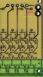
You can break the board up into subsections, which I assume you want to use with subpacks for your setup, and connect the subsections via six wires that make up the opto bus lines, two for the LVC and four for the charger control. These are shown in yellow below.

24-Cell%20LiFePO4%20BMS-v2.3-Subsections.png


These can be thin-gauge wire, as there's not much current to carry. The only other thing you need to do is make sure that each subsection board has the first and last connections to the first and last cells in the subpack. This is the reason for the duplicate cell connection holes (i.e. -- 5/6, 10/11, etc...).

-- Gary

Hey Gary

Could you please specify if pin hole 30 & 31 have to be linked together; Just like the traces showing in the photo for 5 & 6.

Heres a photo from a prior post shoing how my wiring is setup; I basically continued this same pattern onto the second bms board

http://endless-sphere.com/forums/download/file.php?id=17485

thanks

-steveo
 
Hmmm... I'm confused. I just looked at the v2.3 board and the last connection hole is 30. Where are you getting 31 from? Did you mean 20 and 21? I'm guessing yes. :) If so, and you are breaking the board at that point, but still using all 24 channels, I'm assuming you want to have two sub-packs, one 16s and one 8s. Connection 21 needs to be connected to negative side of the 1st block of cells in the 8s subpack.

-- Gary
 
GGoodrum said:
Hmmm... I'm confused. I just looked at the v2.3 board and the last connection hole is 30. Where are you getting 31 from? Did you mean 20 and 21? I'm guessing yes. :) If so, and you are breaking the board at that point, but still using all 24 channels, I'm assuming you want to have two sub-packs, one 16s and one 8s. Connection 21 needs to be connected to negative side of the 1st block of cells in the 8s subpack.

-- Gary

Hey Gary

You got the right idea .. but in my case i'm using 2 24s bms boards for a total of 48 channels ..

So essentially I must connect the 6 wires plus dasy chain pin 30 with the first channel of the second 24s board.. meaning there are actually 7 wires in my case to connect the bms's together to work kind of like a master + slave..

-steveo
 
steveo said:
Hey Gary

You got the right idea .. but in my case i'm using 2 24s bms boards for a total of 48 channels ..

So essentially I must connect the 6 wires plus dasy chain pin 30 with the first channel of the second 24s board.. meaning there are actually 7 wires in my case to connect the bms's together to work kind of like a master + slave..

-steveo

Well, if you have two sub-packs that are connected in series, you don't need a jumper between hole 30 and hole 1 on the 2nd board. All you need is to connect hole 1 to the bottom of the second subpack. Hole 30 does not need to be connected if the 1st pack's positive lead is already connected to the board.

If this is just one big pack, and the positive charger connection goes to the last channel on the 2nd board (i.e. -- next to pin 30 on the 2nd board...), you will need to connect hole 30 on the first one to hole 1 on the 2nd board, and one or the other needs to be connected to the junction of the 24th and 25th block of cells.

-- Gary
 
Crazy Steveo.. 48 series cells on a 5304 :twisted:

Pay attention to avoid your rear tire getting out of the rim with centrifugal force while runing at 88mph!! :lol:

88mph on a steel rim would make beautifull firework!!..

Doc
 
GGoodrum said:
steveo said:
Hey Gary

You got the right idea .. but in my case i'm using 2 24s bms boards for a total of 48 channels ..

So essentially I must connect the 6 wires plus dasy chain pin 30 with the first channel of the second 24s board.. meaning there are actually 7 wires in my case to connect the bms's together to work kind of like a master + slave..

-steveo

Well, if you have two sub-packs that are connected in series, you don't need a jumper between hole 30 and hole 1 on the 2nd board. All you need is to connect hole 1 to the bottom of the second subpack. Hole 30 does not need to be connected if the 1st pack's positive lead is already connected to the board.

If this is just one big pack, and the positive charger connection goes to the last channel on the 2nd board (i.e. -- next to pin 30 on the 2nd board...), you will need to connect hole 30 on the first one to hole 1 on the 2nd board, and one or the other needs to be connected to the junction of the 24th and 25th block of cells.

-- Gary

thanks for clarifying!

will let you know when i charge if everything works well.

-steveo
 
Doctorbass said:
Crazy Steveo.. 48 series cells on a 5304 :twisted:

Pay attention to avoid your rear tire getting out of the rim with centrifugal force while runing at 88mph!! :lol:

88mph on a steel rim would make beautifull firework!!..

Doc

Comeon doc..

I'm only running 40s pack .. not 48s .. i'm not that crazy .... lol ...hmmmm .. ( i can duck tape some batteries to my back) hahah

-steveo
 
fechter said:
Icewrench said:
L V C connection question. The E V Global controller sends a 39 volt , system voltage ,signal to the brake switches and gets 39 volts on the return pin when the brake is applied. I have the lvc leads spliced into the wires for one of the brake switches. Will the boards lvc circuit be ok with this voltage or is this a problem?

The optocoupler outputs are rated for 50v, so it should be fine at 39v.

Tying into the throttle signal would work too, but you need to add a 1k resistor in series with the throttle signal line coming from the throttle.

Hey Fechter

Could you please draw a diagram just to give me a visual on this?

Where exactly do we wire the (brake) & (ground) wire from garys bms to?

My controller has a 5 v brake; when shorted with ground the controller disables
my controller also has a high voltage brake.... when you tough a positive lead on the battery pack .. it cuts power to the controller.
if all else fail i will attemt the throttle take down .. and make sure my connections are 120% secure .. i can't afford to see my bike take off on me.

I measured the voltage of brake & ground testing my bms.. when a cell is lower then 2.1 v the brake & ground go to 0.00v .. when all batteries are above 2.1 .. i get output around .15v .. is this normal?.. i damaged a channel .. but repaired it!! testing the lvc with the 5v brake .. i used a AA battery ... :S .. it blew the channel when i applied the throttle!

thanks
-steveo
 
Hey Steveo

It`s me the guy that melts stuff :mrgreen:
A resistor in line between throttle and controller reduces full throttle input to controller.. not what I want.
What I did was put the resistor in line with lvc output and spliced that into the throttle input to controller.
Did not run it long enough to trip lvc but the throttle was working good.
 
Steveo -- You can use the brake input that you short to ground on the controller. Just connect the GND to the controller ground, and the BMS BRK signal to the this controller brake input that needs to be grounded. The optocouplers on the BMS board are like if you had a bunch of switches in parallel. If any one of them trips, it will ground that Brake input on your controller. This will cause the controller to cut the throttle, removing the load.

The only time you need to do the other option, where the BMS output is used to pull down the throttle signal directly, is when your controller doesn't have a brake input that needs to be grounded to be active. If you are grounding the throttle signal directly, you need the 1k resistor in line with the BMS BRK signal and the throttle line, to limit the current.

-- Gary
 
GGoodrum said:
Steveo -- You can use the brake input that you short to ground on the controller. Just connect the GND to the controller ground, and the BMS BRK signal to the this controller brake input that needs to be grounded. The optocouplers on the BMS board are like if you had a bunch of switches in parallel. If any one of them trips, it will ground that Brake input on your controller. This will cause the controller to cut the throttle, removing the load.

The only time you need to do the other option, where the BMS output is used to pull down the throttle signal directly, is when your controller doesn't have a brake input that needs to be grounded to be active. If you are grounding the throttle signal directly, you need the 1k resistor in line with the BMS BRK signal and the throttle line, to limit the current.

-- Gary

Hey gary

I have wire the bms directly to the 5v brake plug on my controller and it seems to work perfectly! ... more testing when i'm able to ride once the weather is better.

-steveo
 
Ok, so I deleted a cheesey thread i started in the ebike technical forum. It only needed to really answer one simple question I have.

When using a 1k resistor to draw down the throttle signal for the LVC, where/how is a good way to set it up? Seems like an odd question, but I'm worried about it getting hot if it ever gets hot from LVC tripping. So, wrapping it in heat shrink and tying it in with the other two throttle leads is probably not a good idea.

Any suggestions?
 
You put the resistor between the controller and the throttle and pull down on the controller side. The resistor will not get hot, you can wrap it in heat shrink if you want.
The diagram below (courtesy of Justin) shows 3-5k, but I think 1K will be fine. The most it could pass is 5ma with a 5v supply. You don't need a diode either, the optocouplers can't backfeed the throttle circuit. Throttle interface.jpg
 
AHA!!!

That's exactly what I've been looking for!!!

As I did a search for this topic, I found a couple others on here wondering as well.

I just wanted to make sure I was doing it right. The diode was another question I was going to ask about, as I wasn't sure if current would go backwards through the circuit. But, as you state the opto's won't allow that.

Thank you.
 
Ok... I feel really dumb. Is there a location that basically gives the rundown on this particular BMS? I have so many questions and I wonder if there is a 'brochure' or something. I know it's a DIY thing, but things like max current for charging and that kind of thing would be awesome!

Thanks a bunch!
 
My BMS which I only use for charging works fine for 16 channels!
Now I want to use my 16s BMS also use for 15s. So I have populated all 16 channels and I have installed a switch to shorten the positive pin from the 16th to the 15th. Charging is working, but it does not shut down the charging process as it does with 16 channels. Which traces should be opened or closed?
Perhaps fechter can tell me what is missing?
 

Attachments

  • BMS2.3mod.jpg
    BMS2.3mod.jpg
    215.4 KB · Views: 723
manfred59 said:
Charging is working, but it does not shut down the charging process as it does with 16 channels. Which traces should be opened or closed?

You'll have to also open the 'all shunts' line between cell/channel 15 and 16 - the control circuit is waiting for a signal that cell 16 full...
 
Richard will correct me if I'm wrong, but I think all you need to do is cut the trace on the top side of the board, circled in blue below, to stop the charger control logic from waiting on the last cell to finish. This is showing if you were turning a 24-channel verion into 23, but you would simply do the same thing for channel 16 if you want to convert to 15.

15-channel%20BMS%20mod.png
 
Back
Top