Even Newer 4 to 24-cell Battery Management System (BMS)

59.9v should be good.

One thing I've noticed is the two cells on either end of the pack run lower than the rest. This is due to the voltage drop in the wire between the cells and the BMS circuit. The tap wires between cells don't carry any current when things are balanced, but the two end wires (pack + and Pack -) still carry the full charge current.

Use shorter/heavier wires for the two end connections to minimize this effect. All the in-between tap wires can be fairly small since they only carry 500ma max.
 
fechter said:
59.9v should be good.

Use shorter/heavier wires for the two end connections to minimize this effect. All the in-between tap wires can be fairly small since they only carry 500ma max.

Thanks, I never thought about that, I actually am using some wimpy 18 gauge wire for the gnd on the the first cell and + on the last cell and the charger wires as well. it is kind of long too 12" or so.
 
Ok, I have the final-final-final parts list together for my project. We will title it:

"The 24 Channel 1Amp shunt Super Angry Lipo Time bomb BMS"

I figure that an overkill bike needs an overkill BMS
What else would we have to talk about if someone wasn't trying to start fires?

I settled on the 1.5A power BJT that fechter suggested, running at 1A
I selected a 5W 3.9ohm power resistor that I will run at 1A, 4.5W
That is really pushing it for this resistor but I do it all the time at work.
If they get too hot I just wrap them in wet paper towels :shock:

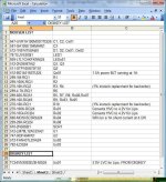
Here is my order sheet.
Everything is in stock.

Order.jpg

Risk assessment / mitigation?

Power BJT: Risk low. May or may not heatsink, probably will if it will fit nicely
Power Resistor: Risk high. May/will require small fan.
4.2V HVC: Risk low, possible the LM431 may turn on at a slightly different voltage
3.0V LVC: Risk low, possible that the board could cut out under heavy load near end of ride.

Good suggestions up till now have been:

* Use a 2.7V LVC so that you can get more out of your batteries.
* Stick with the 500mah shunt current because it is effective and safe
* Run a separate 12V power supply to reduce risk on a 24 cell version
* Tune for 4.18V or 4.19V to make sure a Lipo charger can kick off

I am going to stick with 3.0V to play it safe :cry:
I am going to go with 1A shunt to keep it dangerous :twisted:
I am going to implement the separate 12V supply
I tuned for 4.19V but it does not matter since I use raw power supplies

Thanks for all the help and tips up to this point guys.
I appreciate your work.

-methods
 
Hi everybody :)

I'm currently using 20S2P A123 cells for my ebike and I ran 10.000 Km since 2 years, with DeWalt default packs, including BMS.
I'm using 4 Dewalt chargers, 2 at home, 2 at work.

Once a year, I'm changing one or 2 DeWalt BMS and a few cells because of their voltage at 0V (may be due to bad load balancing by the BMS)

I'm discovering this great forum and I received a kind reply from Gary.

I would like to discuss with people who are using this BMS with such a pack 20S2P A123 :
- which charger ?
- time to charge ?
- way to proceed ...

Regards, Jérôme (from France)
 
nice :p bomb in a box lipo packs lol
 
what is the resistance on the e brake wires supposed to be when the lvc come on?

i get 363 ohms not enough for the continuity beeper on the meter to co on when i short the lvc test pads.

is that normal and how do i get the ebrake wires to cause the beeper to come on?
 
If you put a small 9v battery in series with the beeper and the LVC output, you should be able to make it beep by shorting the test pads. Normally the 5v from the throttle or ebrake circuit supplies this voltage.
 
jcg2a said:
Hi everybody :)

I'm discovering this great forum and I received a kind reply from Gary.

I would like to discuss with people who are using this BMS with such a pack 20S2P A123 :
- which charger ?
- time to charge ?
- way to proceed ...

Regards, Jérôme (from France)

For 20s, you would need around 75v or more for your charger. Any current limited power supply will work. Charge current will determine the charge time. With a 5 amp supply, you can charge in about 1 hour for a 2P setup. You might be able to find switching power supplies that you can put in series to get the desired voltage.
 
Hey Everyone,

Does anyone know when Gary will be re-stocking the boards again?

-steveo
 
steveo said:
Hey Everyone,

Does anyone know when Gary will be re-stocking the boards again?

-steveo

Richard and I are doing a slightly updated version. I'm still working on finishing up the layout changes, but with the holidays upon us, my time isn't all my own. :roll: I hope to get it finished tonight still, and submit it in the morning. That would get the boards back to me by Thursday.

There are two main changes, one to the 12V regulator section, to allow a single board to be used with higher voltage packs (100V+...), and the other to provide provisions for using this BMS with other Lithium chemistries, like LiMn (Sony/Konions, Milwaukee v28s, etc. and LiCo (RC LiPo packs...). A third change is simply to use a cheaper opto part as a replacement for the ILD2s. This new part has a different pinout, so it requires a layout change.

-- Gary
 
GGoodrum said:
steveo said:
Hey Everyone,

Does anyone know when Gary will be re-stocking the boards again?

-steveo

Richard and I are doing a slightly updated version. I'm still working on finishing up the layout changes, but with the holidays upon us, my time isn't all my own. :roll: I hope to get it finished tonight still, and submit it in the morning. That would get the boards back to me by Thursday.

There are two main changes, one to the 12V regulator section, to allow a single board to be used with higher voltage packs (100V+...), and the other to provide provisions for using this BMS with other Lithium chemistries, like LiMn (Sony/Konions, Milwaukee v28s, etc. and LiCo (RC LiPo packs...). A third change is simply to use a cheaper opto part as a replacement for the ILD2s. This new part has a different pinout, so it requires a layout change.

-- Gary

hey gary

thanks for the update, i will check back here regularly untill you restock.

-steveo
 
GGoodrum,

I have a dumb question.

I've read through this thread a couple times now, and can't find something.

Let's say I plug my battery in to charge it up, and then I decide to leave plugged in for say... a month or two during winter when I'm not riding it?

That way, the battery never loses its charge, and would be ready to ride on a whim, when the weather gets better.

I assume this thing is basically acting like a smart charger/BMS, that allows me to leave it plugged in indefinitely?

I hope so, since that's the reason I decided to go with it. But, being an idiot, I never thought to ask until now. :oops:
 
Patriot said:
Let's say I plug my battery in to charge it up, and then I decide to leave plugged in for say... a month or two during winter when I'm not riding it?

....
I assume this thing is basically acting like a smart charger/BMS, that allows me to leave it plugged in indefinitely?

When the BMS senses all the cells are full, it turns off the charging current. Actually, there will be a small charge current still flowing as long as the charger is on due to the drain of the control circuit which will keep the cells above #5 at the shunt voltage. Cells 1-5 will get no current.

From what I can tell, leaving the pack on charge for extended periods will significantly shorten the calendar life of the pack. It would be better to fully charge the pack, then disconnect the BMS so there is no drain at all. A healty pack should hold a full charge for many months. You could top off the pack before you go riding again, which should not take very long.
 
dnmun said:
i was under the impression that it was best to store lifepo4 under partial discharge. up to 40%, and i also know that is the case with nicads, any opinions?

With LiCo-based LiPos, we used to use the 60-70% level as best for long-term storage. When you get new packs they usually come this way. I really don't know the reasoning, but in any case, I'm not sure it applies for LiFePO4-based cells. I've kept many of my a123 and LiFeBatt packs stored at the 100% level, with no apparent problems. Some of these I haven't touched for months, and they remain full.
 
The flat discharge curve of LiFePo4, specially at no load, means that voltage at 90% charge level and 40% charge are just about the same... ( vs the progressive 4.2 to 3.0v slope of LiMn/Co ) so all things considered i leave my LiFE packs 100% full to avoid the potential of a cell going below 2v while sitting on the shelf.

YMMV.
 
i was wondering what kind of enclosures users are using for their bms board i am looking for something to enclose the batteries and bms board in.
 
Ggoodrum wrote:
"... drill out one or two "jumper" holes, both per channel. Same for the higher shunt cutoff, add a resistor and drill out a hole, for each channel. For the surface mount version, we'll just have the resistors already there, and we'll drill out the jumper holes, for a non-LiFePO4-based setup."

Jumper holes -- that's a very clever idea! Thank you. I have struggled with how to do jumpers on SMT boards and had not found a good solution. Hopefully a guy with a Dremel drill is less likely to damage the board than trying to cut a trace with an Xacto knife. And it should be more certain disconnect as well.
 
do you have the schematic for this board?


GGoodrum said:
Yes, that circuit is pretty much it, for the LVC circuit. Just the TC-54, an 820 ohm resistor and the CNY-17F optocoupler, for each channel. In the BMS, and the later versions of the LVC boards I've done, we use a dual-channel ILD2 optocoupler, one for every two channels on the LVC. For the BMS, half of the ILD2 is used for the LVC, and the other half is used for the charger control logic.

Unless you have a space problem, I'm not sure why you would need to separate the LVC out from the rest of the charger control logic in the BMS. The LVC circuits work completely independent of the charge control logic, which is not even enabled unless the charger is connected, and on.

I have an updated, LVC-only board that I have ready to get made, but I'm just not sure there's much demand for just the LVC board. I could do a small run of these, but that makes them pretty expensive, so I'd have to charge about $25-$30 each for them. Here is the layout:

24-Cell%20LiFePO4%20LVC-v2.3a-PCB.png


This uses the same "tear-off" feature to support any number of channels up to 24. It also includes Randomly's active cutoff circuit, which doesn't have to be populated if not used. Actually, you can simply break off how ever many channels are needed from the right side of the board, if the active cuttoff is not needed. If active cutoff is needed, by using a pair of 4110 FETs, it will handle 100A+. It draws next to nothing in standby current.

Anyway, if there is enough interest, I'll get these done this week.

On the BMS front, Richard an I are working on a slightly updated version. The big change here is that the new version will now also support using other Lithium chemistries, like LiMn/LiCo, simply by cutting a jumper for each channel. Actually, the jumper will be simply a through-hole connection pad, so all that need to be done is the holes would need to be drilled out to break the connection. What this will do is change the LVC cuttoff from 2.1V up to about 3.0V, and it will change the shunt cutoff from about 3.68V to 4.18-4.19V.

We are also adding a couple parts to the 12V regulator circuit so that much larger pack voltages can be supported. I think the limit right now is about 72V. but now it should be able to support up to a 48s/144V pack configuration.

Finally, I'm thinking about adding Randomly's active LVC cutoff circuit to this version, as I continue to get requests for this feature for some who want to do 12V and 24V SLA replacement packs, which need to be stand-alone (i.e. -- no ebrake/throttle cutoff on the controller...). What I'm thinking is that can add it to the far left part of the board, and add the "tearoff" holes for those that don't want active cutoff. The other option is simply to do a separate 4/8-channel version, with the active cutoff.

We are alos working on the surface mount cersion of the BMS. After we fully test the new version, we'll finish up the conversion, and get fully populated boards done. This will still be a couple of months away, before we can actually have them ready to sell, but this is the path we are on. :)

Anyway, I hope to get this new version in for production early this coming week. Because we are so close, I've decided not to do another run of the current version (v2.2), so for those still waiting for these to be back in stock, you will have to wait another week, or so.

-- Gary
 
ErikK said:
Jumper holes -- that's a very clever idea! Thank you. I have struggled with how to do jumpers on SMT boards and had not found a good solution. Hopefully a guy with a Dremel drill is less likely to damage the board than trying to cut a trace with an Xacto knife. And it should be more certain disconnect as well.
Not a great solution but I've used zero-ohm 1/8W through-hole resistors as jumpers. Just solder the lead ends down onto small bare pads. The resistor body holds everything a bit off the PCB.
 
Yes, I thought about the zero ohm resistor approach. The through plated hole method will be cheaper. I've used a drill bit in a pin vise to drill them by hand. You don't have to drill all the way through either, just making a divot in the top of the board is enough. To un-do the cut, you can solder a piece of wire in the hole.
 
ejonesss said:
do you have the schematic for this board?

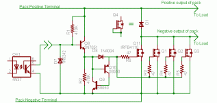
No, I don't seem to have that one. Here's a partial that's similar: The cell circuits are just a TC54, a resistor and the optocoupler. This is Randomly's design.
LVC Active Cutoff-revised.gif
 
ErikK said:
Jumper holes -- that's a very clever idea! Thank you. I have struggled with how to do jumpers on SMT boards and had not found a good solution. Hopefully a guy with a Dremel drill is less likely to damage the board than trying to cut a trace with an Xacto knife. And it should be more certain disconnect as well.

This was Richard's idea, which I too think is quite clever. With the through-hole version of the board, they take up no additional space. The jumper hole is directly under the resistor. You either leave the resistor out and don't touch the jumper hole, or you drill out the hole and add the resistor. Pretty simple, and no extra work for the standard LiFePO4 version.
 
thanks. the main thing i wanted to see is how the active cut off part was constructed so a similar one could be connected to the ebrake out on the current bms.


fechter said:
ejonesss said:
do you have the schematic for this board?

No, I don't seem to have that one. Here's a partial that's similar: The cell circuits are just a TC54, a resistor and the optocoupler. This is Randomly's design.
 
these cells at http://www.rechargeablelithiumpower.com/oscommerce2/catalog/40138-lifepo4-cell-p-28.html


is the cut off of the bms safe for these cells?

on the a123 dewalt cells they say the cut off on discharge is 1.6

http://a123systems.textdriven.com/product/pdf/1/ANR26650M1_Datasheet_AUGUST_2008.pdf

so there is some margin of safety there.

is it a standard for all manufacturers to set the numbers a little above the failure point to leave room for safety?

for example let's say that a bike tire tube pops at exactly 100 psi the manufacturer will say the max is 60 psi.

that leaves a 40 psi margin of safety.
 
Back
Top