Farfle's Mk.5 Super badass outrunner

Farfle

100 kW
Joined
Jun 27, 2010
Messages
1,759
Location
Redmond OR
Hello all, I am about ready to start designing a new Outrunner for next years race bike. And would love your input.

My goals:

Less than 300mm outer diameter
Less than 100mm total width
Around 100 horsepower output
Less than 60lb or 27.2 kg
Liquid cooling is ok
Total cost under $3500

Techniques that I want to leverage:

Hairpin TIG welded solid-slot windings for > 90% copper fill, and very high thermal resistance.

An alloy of lamination steel that supports high flux densities. (Hiperco etc...)

Segmented magnets

Laminated back iron.

I have run some Ideas thru both femm and emetor, and have a few different approaches that I would love to run past you guys:

1st approach:

12t 10p single or double layer wind
Pros: familiar, .966 winding factor
Cons: needs substantial back iron, and has a half-ass Sine/trap BEMF.

2nd approach:

30t 10p single layer integer wind

Pros: 1 winding factor, near perfect trapaziodal bemf (controllers are cheap) and easy to wind solid slot.

Cons: lots of yolk iron required, totally unfamiliar territory.

Trying to keep the flux gap speed up while keeping the pole count low, to keep my controller options as open as possible.

Anywho, if anyone has any bright ideas/inputs, I would LOVE to hear them, as this is a shot in the dark for me
 
Ill post up femm/emetor shots of both approaches later tonight.
 
Farfle said:
2nd approach:

30t 10p single layer integer wind

Pros: 1 winding factor, near perfect trapaziodal bemf (controllers are cheap) and easy to wind solid slot.

Cons: lots of yolk iron required, totally unfamiliar territory.

You won't necessarily need segmented magnets or laminated rotor for 30t 10p

Lots of yolk iron isn't so much of a disadvantage for an outrunner......

Extra endturn losses from integer winding won't be a disadvantage for solid slot.
 
Farfle said:
1st approach:

12t 10p single or double layer wind
Pros: familiar, .966 winding factor
Cons: needs substantial back iron, and has a half-ass Sine/trap BEMF.

Cons:
Only one winding symmetry.
Higher magnet losses for the single layer winding (which has the 0.966 winding factor).
 
Thank you miles

As far as the integer wound motor goes, the bemf is almost perfectly trapezoidal. but when run with a BLDC input in emetor, the torque ripple is pretty bad. I guess I thought if the flux linkage was very trapadoidal, that it would be smoother than that.

And yes, with only one winding symmetry for 12t 10p, emetor wont simulate it, even with credits. So I would just be shooting in the dark with femm flux density analysis.
 
Farfle said:
As far as the integer wound motor goes, the bemf is almost perfectly trapezoidal. but when run with a BLDC input in emetor, the torque ripple is pretty bad.
What is "pretty bad"? I sampled for torque ripple at no-load and max.Eta.

What is the max. rpm you intend running this motor at?
 
I am aiming for 5000-6000 RPM, but if I can get the power I need a a lower rpm, that would be great. The controller options I have in mind either the scott drive 450a 400v controller (not using all the voltage) or the 1000A 120v kelly, or if the stator configuration allows it, twin 600a kelly controllers.
 
Miles said:
Farfle said:
As far as the integer wound motor goes, the bemf is almost perfectly trapezoidal. but when run with a BLDC input in emetor, the torque ripple is pretty bad.
What is "pretty bad"? I sampled for torque ripple at no-load and max.Eta.

What is the max. rpm you intend running this motor at?


While running Emetor, I was trying to compare the linear and non-linear simulations. In the linear sim, it has a 16% torque ripple, and in the non-linear sim it is 66% :shock: . Messing with the tooth shape and magnet coverage to see if I can get it to smooth out a little more.
 

Attachments

  • iwor-1 nonlinear.pdf
    799.5 KB · Views: 182
  • iwor-1-linear.pdf
    779.2 KB · Views: 119
I have gone thru 17 different non-linear sims so far, and have torque ripple down from 66% to 26%, the airgap flux up from .8t to 1.1t, (which I assume is good, its raising the BEMF voltage by almost 20v) and traded the magnets from n45 to n42sh. Am I headed the right direction? :pancake: :pancake: .
 

Attachments

  • iwor-17-nonlinear.pdf
    799.6 KB · Views: 116
I think so..... :)

I like where this is headed. Solid slot with tig welded aluminum?
 
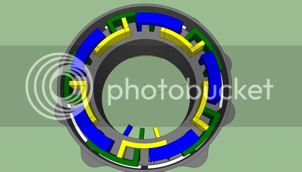
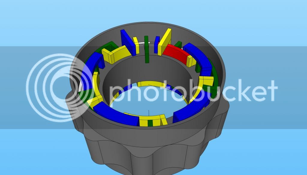
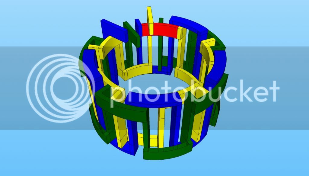
ok, here is a rough drawing of the motor. The windings look complex, but will actually be very easy to construct.

Overall dims are 12 inch dia x 7" thick can end to can end.

The copper wire is actually 25mm by 6mm solid bar.


Beautiful. Going to be low inductance.
 
liveforphysics said:
Beautiful. Going to be low inductance.


I am hoping its not too low. Ill run it thru emetor in sine wave test to see if I am even in the ballpark of driveable.
 
hmm, emetor is spitting out 0.005797 mH or 5.7uh. thats really really really low. bugger.

Back to the drawing board!
 
Just do what Ultramotive did with their Carbon motor. Claim amazing power to weight, and only casually mention in passing the requisite 15 kg worth of induction coils... :lol:

Love the idea though. Perhaps running lower voltages at higher currents will help? Aim for at least two turns :)

Edit - I'm from the department of redundancy department...
 
The problem is that that particular design benefits greatly from being solid-slot. great enough to make it worth it, but it qouckly fades if you go back to normal winding wire and multiple turns :?
 
I'm sure there's still a way of getting two turns worth of copper bar in there and welding it up all the same. Load it like a twin-row revolver and weld up the ends?
 
Bugger. Emetor flat refuses to simulate any of my lower-pole count ideas. After doing some research, I have come up fruitless on any equations relating magnet coverage to optimal BEMF shape. :cry: .
 
looking at most high performance permanant magnet motors, I am seeing some common trends. TONS of stator teeth, and lowish pole counts. Sometimes solid slot windings, and sometimes standard round windings. :pancake: .


UQM motor, wtf, look at all those little teeth:

http://chipyates.com/yahoo_site_admin/assets/images/Chip_6.127224154_std.JPG

remy motor:

http://www.blogcdn.com/green.autoblog.com/media/2010/02/remy-motor.jpg

Chevy spark EV motor, lots of teeth, only 10 magnets (kinda):

http://static.progressivemediagroup.com/uploads/imagelibrary/ChevySparkEVElectricMotor03.jpg

http://www.hybridcars.com/wp-content/uploads/2013/04/Chevy_Spark_EV_Motor_2-668.jpg
 
Farfle said:
After doing some research, I have come up fruitless on any equations relating magnet coverage to optimal BEMF shape. :cry: .
Nothing I found was of any use, either. You just have to keep iterating... Did you try values between 125 and 130 degrees?
 
Miles said:
Farfle said:
After doing some research, I have come up fruitless on any equations relating magnet coverage to optimal BEMF shape. :cry: .
Nothing I found was of any use, either. You just have to keep iterating... Did you try values between 125 and 130 degrees?


problem is, it wont simulate it. sits there, and gives me the "this configuration has too few symmetries, run it in pro" speech. And when I run it with the non-linear test (have 17 credits left) it just sits there for 10+ mins beforegiving a vague "simulation has failed" error. Thankfully it is not charging me.
 
I wonder if scaling it down would at least get me in the ballpark with magnet coverage for a given stator configuration, and then I can refine the flux densities in FEMM.

Anywho, its 2:00am here. Time to sleep on it a little bit. :roll:
 
Back
Top