oatnet
1 MW
All of the LiFe packs I bought have come with what I call the "Flintstones Charger" - the big white plastic 1950's-looking charger with 8 - 12 subchargers inside. I got two more of them with the individual LiFe Cells I bought from Andy/FalconEV, so I have been looking more closely at how they are wired. I think I have found a serious design/implementation flaw with them, but need someone smarter to confirm it.
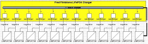
These Packs are charged with a single positive lead and (12) negative leads. Each charger has up to (12) individual-cell subchargers, each with dedicated '+' and '-' solder-points. However, only the '-' has a wire soldered to it, running to the '-' pole on each cell. The circuit is completed with a single wire from the 1st subcharger's '+' solder point to the packs '+' main discharge lead.
This single '+' lead is what disturbs me. I think that means the subcharger furthest from the '+' lead is actually charging 12 cells in serial, the next one 11 cells, and so on. I also think the cell closest to the '+' lead is getting too much current from all 12 subchargers, and thereby overcharged even when its sub-charger shuts off.
Am I correct in thinking this is way wrong? That both terminals of each cell should be connected to a dedicated subcharger? I can't imagine how a pack could ever be 'balanced' like this, and it certainly explains why it takes SOOoooo long to charge a pack.
Unfortunately, I think that the charger would short if both terminals are wired AND the cells were wired into a string. I wired (2) cells to (2) subchargers using both the '+' and '-' solder points, and they each saw @3.7v, so those charging points work. When I emulate wiring them together in a string by putting a multimeter between the '+' of one cell and '-' of the next, I see 7.4v, so they are not electrically isolated.
My spectulation: these chargers were designed to be combined with a discharge BMS. Instead of being wired into a serial string, each cell should be independently wired to the charge and discharge BMS's, and the discharge BMS would sum the cells to produce 42v. When the discharge BMS's failed (they are crap), chinese pack builders decided to wire the cells in series. When they found out that shorted the charger, they adapted it to the current wiring scheme, and figured the stable LiFePO4 chemistry would suck up the abuse in the short term. When the charging abuse starts to fail cells, the consumer has had the pack long enough for the root cause to be murky.
My current plan is to wire both terminals from each battery to a 24 pin connector using 10ga wiring. I'll build two matching 24-pin connectors, one that pulls both terminals from the charger to connect each cell, and another that connects the cells in a string and has +/- leads at each end. That means I need to build (6) 24-pin connectors for a 72v (84v) pack - ouch.
-JD
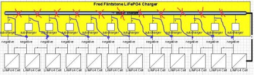