major said:
Miles said:
halcyon_m said:
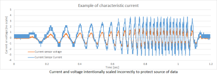
Something called 'characteristic current' is the most relevant parameter, which is the current the motor will put into the windings if you short them at any speed above some minimum value. A motor with a characteristic current equal to the current rating of the motor has a constant-power-to-speed ratio that is effectively infinite, meaning you can get the rated power at any speed because it is possible to push back on the magnets completely with the current available from the controller.
Thanks halcyon.
I also found that to be an interesting paragraph. Most of those who read it may miss the point that
power-to-speed ratio is torque. So is halcyon saying motors have infinite torque?
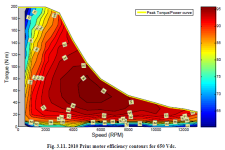
I guess I should have been more explicit. I did -not- mean that motors have infinite torque. I meant that the ability of a motor to deliver constant power (where torque decreases while speed increases) is available over a range of speeds. For example, look at the 2010 Prius motor shown below. (it's from the oakridge national lab report on the 2010 prius)
The key elements to not here are that:
1) the base speed is around 3200RPM. This is the maximum speed at which full torque can be applied. In this case torque is limited by the current rating of the inverter.
2) the torque decreases above 3200RPM, as the inverter is only capable of delivering so much current, and some current has to be dedicated to 'pushing back against the magnets', something referred to as negative d-axis current, where the d (direct) axis is in line with the magnets. Only the remainder of the current can go in the q-axis (quadrature axis, 90 electrical degrees from the d-axis, aligned between magnetic north and magnetic south), where the d and q axis currents add as orthogonal vectors to be less than the current limit of the inverter. Example: if current limit is 100A, and 60A is needed for flux weakening, then only 80A can be used to create torque in the q-axis, and this comes from the equation where: square root of (60^2 and 80^2) is 100. Remember the 3,4,5 right triangle?
3) the characteristic current for this motor is slightly more than 1, which is evidenced by the torque capability decreasing faster than the speed is increasing, giving less and less power as speed increases beyond 3200RPM. However, not all is lost. There is still 50kW available at 6000RPM, where there was 64kW available at 3200RPM.
4) imagine if you only had the use of this motor to 3200RPM without flux weakening and you had to shift gears to get to higher speeds. Not only would you increase the mechanical complexity, but you would also miss out on being able to operate the machine in the area of peak efficiency. Ok, so this is cheating, but only a little, because the machine was designed to take advantage of flux weakening, so the peak efficiency could have been designed at a lower speed, but this was a very well designed machine that is able to provide nearly constant power over a 4:1 speed range.
I hope that clears up what I mean by constant-power speed-range (aka CPSR). Modern gear boxes have about a 5:1 range if I'm not mistaken, so if you have a machine with a 5:1 CPSR and a decent efficiency throughout (check out the 90+% efficiency at higher speeds!), then why introduce a multi-gear transmission with added weight?
Of course there are other practical considerations to using a gear box, but I'll let someone else argue that side for now.