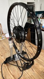
First Hub Wheel Build

Almost have me talked into it. It is a pain setting up all the points on a bike. When people ask "Do You Need a Stand" answer No.

Have build 3 wheels and at the minimum have 3 more to build. Guess if you don't need it any more you can sell it here in ES.
 
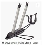
I've ordered in a truing stand, nothing special, but I do like the idea of being able to sit at my kitchen table while learning to true.

WheelTrue.JPG
 
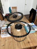
Some progress today, I spoked up the hub by copying an existing wheel I have.

I used a couple of rolls of tape to lift up and hold the hub in place, then various books to raise the rim up to the right height.

I think I must have made just about every mistake you can make which is to be expected first time around I suppose.

BFC07966-EBA1-423F-ACE2-F56D0270F739.jpeg

It was trickier than I expected, some of the spokes had to be bent a little to get them into the eyelets on the rim.

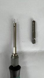
I used two nipple drivers, one that slots into a screwdriver handle and another that fits in a drill.

0F3390DA-B76C-4B3B-AE32-AB06072D6DC9.jpeg

It was quite difficult get some of the nipples to line up with the spoke, which made it feel like the nipple was going to cross thread.

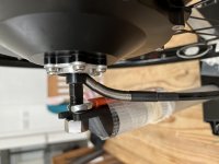
I then put the wheel in my truing stand to find the U notches the axle fits into are so wide that the axle rocked around which made it useless, so I taped a couple of 10mm spanner’s to the arms so that the axle could slot into place.

1814D9A6-DDAC-4F43-B7CC-DA956A5CD396.jpeg

The drill bit nipple driver has a 1.5mm spigot out the top, the idea is to get all the nipples to the same depth as a starting position.

This seemed to work ok but literally the last nipple I tightened snapped, it was of course the only thing I didn’t order a spare of, so it will be a few days before I get some more.

30A47065-6099-4AD4-AF42-51843802EF6E.jpeg

Once I get these I will move on to truing the wheel.
 
My first wheel build was with a big DD motor 45 mm but I use basically the same technique you are using for holding the motor and rim in place prior to the spokes remember just don't cross spoke the valve..
My second bill went better my third bill I put the washers under the spoke heads and it came out near perfect till I hit a couple ruts in the road.
I was told I could use the same spokes and nipples so I did with the same washers it didn't work out very well so I'm building a wheel stand . Big bump in it almost the same bump I had before with the old rim. I probably at a minimum should have replaced all the washers and probably replaced all the spokes and nipples. I don't know what the problem is but it has the same bounce as previously maybe the spokes are bent a certain way ?
 
I clamp an old fork to my desk for a stand. It helps that I have both a 100mm front fork and a 135 mm fat bike fork, so I can do rear wheels. I believe I get a good wheel, because I can spend all day on it, For 175mm, which is rare, I flip a bike upside down,
 
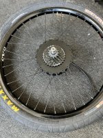
My first wheel build is complete, it wasn't as hard as I was expecting, here are some thoughts:
IMG_1726.jpeg

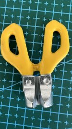
I ended up buying a comically expensive sapim nipple wrench, only to find that I couldn't use it, for two reasons.
The gap between the two 'blades' on the wrench isn't big enough to fit over the sapim e-strong spokes without forcing it, which scratches black spokes.
IMG_1727.jpeg

The angle between the nipple and spokes is not as straight as it would be with a standard wheel because of the hub motor and so you can't slide the wrench down onto the nipple.

I ended up doing 99% of the truing using a nipple driver rather than a spoke wrench.
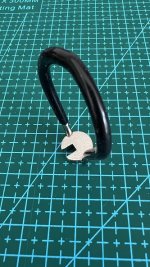
I have now purchased a cheap nipple wrench which will do the job in future.
IMG_1728.jpeg

I have also purchased another nipple driver with a 2.5mm stub which is great for getting all the spokes into an equal starting position. The 1.5mm version I used was just a bit too short meaning the spokes were too tight for starting off with.
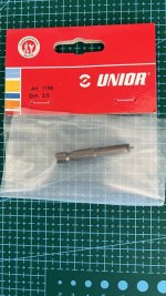
IMG_1729.jpeg

I haven't got a spoke tension meter but all the spokes seem nice and tight, we'll see what happens on first ride.

I'm glad I got the truing stand, it made everything much easier, finished wheel is within 1mm laterally and radially.

Spoke wind up was definitely a thing, I made sure to de-stress the spokes as I went along with a wooden spoon handle similar to the Grin hub building video.

There is a significant amount of adjustment depth within a nipple, several millimetres, next time I would order spokes 1mm smaller than the calculator says, as this would have made lacing the wheel just a little easier.


I haven't actually tried the wheel yet as I want to use a particular disc brake rotor I have, but the rotors don't work with avid bb7 / bb5 as they catch.

I'm thinking I might try some Clarks hydro's which look like they would work although can't be sure.
 
I’m a total convert to hydraulic brakes.

I can’t believe I’ve spent so many years mucking around with avid cable brakes, so many hours troubleshooting rubbing brake pads.

These Clark M2 hydros are amazing and insanely cheap as well. For £40 / $50 you get two brake levers, two brake calipers, two hoses, two disc rotors 160 & 180, two brake mounts for the rotors, two brake pads and it all comes pre-bled so you just take them out the box and attach to your bike.

The callipers are pushed in from both sides which makes them trivial to align as you just squeeze the brake lever and tighten the bolts down and bingo, perfect alignment. No rubbing.

I’m never going back to cable brakes.
 
So I almost had a catastrophic failure with the new wheel on first test.

I installed the new motor on a hard tail MTB I have using a substantial torque arm which I picked up from a forum member several years ago. I bought several of them, I think they were water-jetted and are obviously steel.

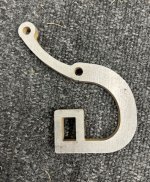
TA.JPG

When I tested the throttle I knew something was wrong, I spotted the motor cable was wrapped around the axle.

We all know this happens when the axle spins in the dropouts, I was very confused at first because the significant TA should have prevented this.

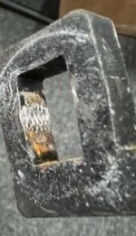
TASpin.JPG

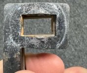
After taking everything apart I was amazed to find the hole the axle goes through on the TA had been pushed apart which allowed the axle to turn.

TASpin2.JPG

I don’t know if it’s a bad design, incorrect steel type or just the motor controller combo is pushing out very high torque.

I’ve ordered a 5mm thick TA to test fit, if it’s suitable I’ll get another for TAs on both sides.
 
Last edited:
If there is any slop in the arm's hole, so that the flats can wiggle in it, especially if the rounded hole ends are farther apart than the actual axle ends so there is a gap, then sufficient torque on that tiny radius can quickly damage and spread (or cut thru) an arm's flats.

The best TAs will have holes that are an exact fit over the axle, such that it may need to be tapped onto the axle, and be unable to wiggle or move at all, with zero gap between the TA flats and the axle flats.

At least some of the forms of waterjet, plasma, etc cutting dont' cut perfectly flat level surfaces, but rather make slightly bevelled ones, so that the entire flat surface does not contact the axle, only a very thin edge of one side's flats. For this type of cutting, it could be better to have them cut a teensy bit small, then machine the flats out carefully to the exact axle flat width of the specific motor they're being used on.
 
"I don’t know if it’s a bad design, incorrect steel type or just the motor controller combo is pushing out very high torque."

At first glance, that TA sure looks nice, suitably thick, nicely finished (at least from the photo).

My guess is that the (rectangular) hole was quite a bit too large, unable to securely grip the axle flats.

TA really needs to be pinch-clamp (best?) or at least interference fit (technical term) that-- as AW states above-- needs to be tapped into place with a small hammer or similar. Can be a PIA hampering wheel removal but that is one of the tradeoffs for preventing axle spinout.

When you get your new TA, if it is not interference fit it may be susceptible to the same problem.
 
So I was told I could use my old spokes to replace a new rim. No.
Had a bented rim and used the old washers, spokes and nipples. I didn't work. I retrude it. Still a hump in the new rim. It seemed transfer from the old rim from the washers and spokes from the old rim I got almost the same bulge.
So brought new spokes, nipples and washers. Spaim 13/14 and will try again later. The only thing the same will be the motor.
I will never try to lace a new rim on a motor with old spokes and nipples that had a bend in it and tried to use the spokes and washers in the same position as before. They have memory.
 
"I don’t know if it’s a bad design, incorrect steel type or just the motor controller combo is pushing out very high torque."

At first glance, that TA sure looks nice, suitably thick, nicely finished (at least from the photo).

My guess is that the (rectangular) hole was quite a bit too large, unable to securely grip the axle flats.

TA really needs to be pinch-clamp (best?) or at least interference fit (technical term) that-- as AW states above-- needs to be tapped into place with a small hammer or similar. Can be a PIA hampering wheel removal but that is one of the tradeoffs for preventing axle spinout.

When you get your new TA, if it is not interference fit it may be susceptible to the same problem.

Well the new TA turned up, the flat to flat distance is stated as 10.17mm which I suppose would be alright for an axle with 10mm flats.

However, when I measure my TA distance I get around 10.2mm and when I measure my axle with digital calipers, my axle flats are more like 9.98mm.

Doesn't sound like a lot, but it's not tight at all, it easily rocks back and forth, I can't use this TA.

I've looked all over but can't seem to find a TA with gap small enough to purchase off the shelf.

I do have a couple more TA's from the same guy as the original one I used and they are small enough, I had to file down the inside gently until I could just tap it on.

I would really like to use TA's both sides though, as I get the feeling from the little throttle action I did use, that this is a high torque setup, but the gear side is awkward to mount anything, no mounting points. Might have to try a jubilee clip even though I dislike them.
 
So I was told I could use my old spokes to replace a new rim. No.
Had a bented rim and used the old washers, spokes and nipples. I didn't work. I retrude it. Still a hump in the new rim. It seemed transfer from the old rim from the washers and spokes from the old rim I got almost the same bulge.
So brought new spokes, nipples and washers. Spaim 13/14 and will try again later. The only thing the same will be the motor.
I will never try to lace a new rim on a motor with old spokes and nipples that had a bend in it and tried to use the spokes and washers in the same position as before. They have memory.

Trust me, it's not the spokes or nipples. It's your method. I've laced over to new rims or otherwise reused spokes hundreds of times (did it at work just yesterday), and it always works just fine. It becomes complicated if spokes have been replaced and there is a mix of lengths in the wheel. Even then, it's completely feasible, but it takes closer attention and more time to execute.


Still, there's nothing wrong with using new spokes. It's usually more pleasant building that way.
 
However, when I measure my TA distance I get around 10.2mm and when I measure my axle with digital calipers, my axle flats are more like 9.98mm.

Doesn't sound like a lot, but it's not tight at all, it easily rocks back and forth, I can't use this TA.

I've looked all over but can't seem to find a TA with gap small enough to purchase off the shelf.
You might be able to hammer in some shim material. Depending on thickness required: tin can scrap? Piece of old tape measure? Actual shim stock?

I do have a couple more TA's from the same guy as the original one I used and they are small enough, I had to file down the inside gently until I could just tap it on.
So was the original like this? Interference fit that you had to tap it into position? If so, and it still rounded out it must be too soft. Most axles are not that hard.
 
Well the new TA turned up, the flat to flat distance is stated as 10.17mm which I suppose would be alright for an axle with 10mm flats.

However, when I measure my TA distance I get around 10.2mm and when I measure my axle with digital calipers, my axle flats are more like 9.98mm.

Doesn't sound like a lot, but it's not tight at all, it easily rocks back and forth, I can't use this TA.

I've looked all over but can't seem to find a TA with gap small enough to purchase off the shelf.

I do have a couple more TA's from the same guy as the original one I used and they are small enough, I had to file down the inside gently until I could just tap it on.

I would really like to use TA's both sides though, as I get the feeling from the little throttle action I did use, that this is a high torque setup, but the gear side is awkward to mount anything, no mounting points. Might have to try a jubilee clip even though I dislike them.
I break off a small piece of this type of razor blade, which is about 0.229mm thick. I put the sharp edge between the TA and flat, and tap it in to fill the gap. My left side axel is cut slightly narrower than the right, so I only use the shim on that side.

510u1pq3LPL.jpg
 
Well the new TA turned up, the flat to flat distance is stated as 10.17mm which I suppose would be alright for an axle with 10mm flats.
That's actually too large a gap. You want a 10mm (or less, for interference fit) wide hole for a 10mm axle flat width. Any slop means the axle can rock back and forth in it, and that only the tiny edge where the flats meet the hole at an angle are actually doing anything to stop rotation.

E-HP's razorblade shim method can work (I've used that, and other materials, to work with general success).

Note that with the rectangular-ended arm you have had problems with, it could just not have enough metal (and/or not hard enough) to resist bending under the condtions you have there. Remember, the entire torque of the motor is all focused on the tiny area of the flats that are in contact with whatever the axle passes thru, and anytime it doesn't actually contact the whole surface area it is then all handled by just the *edges* of the axle flats where the threads stick up, and thus only the tips of those threads, which is why it can carve threads into the faces of the arm holes or dropouts, etc.

It's tough to find a TA that actually fits an axle perfectly unless you get one that's too small and then file or machine it carefully until it is a perfect fit, since axles may be differently machined even on each side of the same motor. :(

A pinching or clamping torque plate would be the best option, but these usually have to be custom-made for each bike. However, Grin Tech's latest newsletter indicates they will soon have available a clamping TA that should fit most bikes.

NEW Torque Arm Series​

Our long serving V2, V3, and V4 torque arms are getting a significant overhaul with the upcoming introduction of three new models:
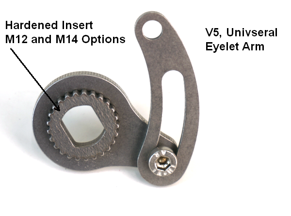
V5 Torque Arm Image

Torque Arm V5 will be a universal eyelet arm that works on both front and rear installations and features a toothed core made from exceptionally hard metal alloy that resists deformation.
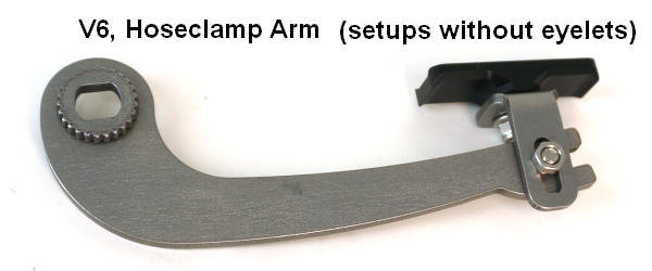
V6 Torque Arm Image

Torque Arm V6 is a universal hose clamp arm for both front and rear installations, for bikes that don't have a suitable eyelet hole near the dropouts.
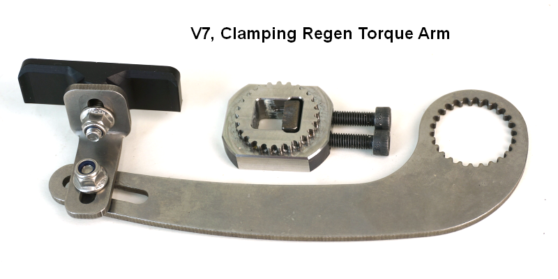
V7 Torque Arm Image

Torque Arm V7 is a fully CNC machined clamping torque arm that puts over 3300 pounds of clamping force on the axle flats. It ensures zero axle wiggle and is designed explicitly for systems with regen.
Torque Arm Testing Video: We'll be producing a video showing the rigors of regen testing and the results. It is significant stuff for all you regen lovers out there. Watch before you buy! Stay tuned to our Youtube or Instagram Channel for that one.
 
Last edited:
However, Grin Tech's latest newsletter indicates they will soon have available a clamping TA that should fit most bikes.
I noticed Grin describes the inserts as being made of hardened steel. Has there been much discussion on the forum about heat treating either purchased, or custom made/mild steel torque arms?
 
Some, I don't recall which threads, except in the torque arm picture thread or maybe it was my SB Cruiser thread, where someone had suggested I do so to my problematic not-quite-thoroughly-pinching-dropouts some months back, IIRC. (I think it was suggested I peen the dropout faces, for instance). (I made them better at pinching which appears to have solved the problem, instead).

(that was the right-side dropouts, the leftside motor is still using the original version but it's axle is not as hard as the rightside motor and is slightly larger diameter so slightly more mating surface area/lower torque at the edges, and I used a tap-in shim on the outboard non-pinching side that I did not use on the outboard non-pinching side of the rightmotor. )
 
Time to go to harbor freight get a 4-in grinder and a cut-off wheel this thin one get a piece of steel 3/8 draw something on there cut it out. The last thing you can easily weld two nuts on both sides of the gap drill out one nut and then you have a clamping torque arm.
Go to the muffler shop and have them weld on two nuts. It will last a lifetime and it doesn't matter how your slot is position as long as you draw it up in a way so you can attach it to your frame with hose clamps.
 
Get the 1500 watt kit if it has a 35 mm wide stator I would like a 40 amp controller but 30 is better. A display so you can see how much amp your hours you taking out of the battery or learn your voltage and don't hit LVC leave something in the tank.
 
Get the 1500 watt kit if it has a 35 mm wide stator I would like a 40 amp controller but 30 is better. A display so you can see how much amp your hours you taking out of the battery or learn your voltage and don't hit LVC leave something in the tank.
Or about 45volts for 14s. Once you learn your battery you can feel that it's losing power also. Because of lower voltage and use.
 
All sorted now, using two TAs both of which I filed down to perfect fit the axle flats.

My next question is around using one throttle on two controllers.

I’ve seen how this is done normally with the signal cable split off to the second controller.

This new setup I have uses Higo connectors like this:

64BFA705-C5F8-4192-89BC-478727D3960D.jpeg

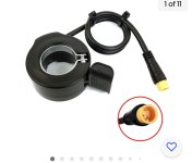
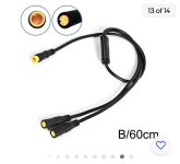
I notice you can get a splitter cable which is advertised as a Bafang gear sensor splitter:

64E62A23-53ED-4C40-A6FF-E4B775A4C540.jpeg

I’m wondering if I can use this ?

Edit: Actually I don’t think the controllers would like sharing the positive and ground lines that go to the throttle?
 
Last edited:
Back
Top