Admiralrofl
10 mW
- Joined
- Jan 25, 2022
- Messages
- 27
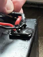
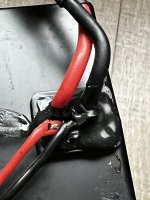
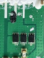
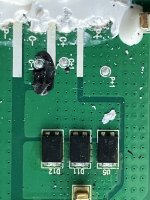
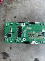
I had trouble probing with a multimeter but I can say the c+ goes through those 3 smd components which are labeled d on the pcb so I’m guessing their diodes or pre charge resistors. then after there looks like a 10a fuse and then that trace after that appears to connect directly to the p+ trace. I’m wondering if that maybe you are right and it is a single port bms but they added this circuitry in purely to prevent sparking when it’s connected to a charger. It would make sense as these batteries are used in ve0 rental e-bikes that are charged a lot and it would be bad news if they charge port got carboned over from the frequent charging.P+ and P- pads, with separate C+ and C- means that you have both positive and negative wires for each port separately exposed there for connection to the outside world. In the typical cheap BMS we see in most non-OEM ebike packs, this means they're separate ports...but not always, even there. And in OEM packs like these, that marking can just be for the service manual / servicer to access and know what they are looking at, easier connection for factory builds, etc.
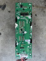
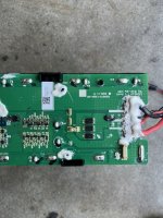
Is the C- (or C+) electrically connected to the P- (discharge) (or P+) pad (even if it is thru diodes), on the load side of the FETs? If it is, then they're both switched by the same set of FETs, and it's still a common-port BMS, and is designed to charge / discharge either way (simply using separate external cables for the easy install and wiring in the OEM device using these packs).
I can't tell from the visible circuitry in the images (as there are traces on the back I can't see, and I can't see the p/n's on all parts).
If there is no electrical connection, and there are separate FETs not seriesed together for charge and discharge, then it's a separate-port BMS, and it would be safer to not charge thru the discharge port and vice-versa.
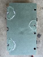
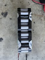
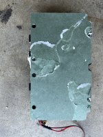
I am no bms expert. I tried to take some closer photos so maybe people with better understanding can rule in. I’d be happy to be wrong as it would make some wiring much simpler for me.
Attachments
Last edited: