Flipsky with 24S?

rg12

100 kW
Joined
Jul 26, 2014
Messages
1,591
I presume you mean 24S Li-Ion 100.8V, and not 24S Li-Fe 87.6V?

The original VESC 100/250, which is what the 75100 is based on, is specified up to 22S and it uses 200V rated caps, so I think you are quite fortunate that your 75100 with it's 100V caps is working at all at 24S!

At steady state before you even turn the motor, you are already operating at or over the max voltage of the capacitors. When you start to turn the motor, you start to generate inductive switching transients which can easily exceed 110-115V. The longer your battery wires are, the higher the transients are. This significantly raises the danger of blowing capacitors and mosfets. If that happens at the worst case it could short-circuit the pack. I hope you are running a BMS with fast overcurrent protection! :flame: :shock:
 
rg12 said:
and was wandering if this version:
https://www.aliexpress.com/item/100...mmend-sku;is_freeshipping:null;trade_order:14
may also work with 24S as it also has 100V caps but advertised as 16S/75V

The FlipSky 75200 will definitely not work on 24S Li-Ion as this esc is based on the VESC 75/300 which has a max 16S design.
Both Flipsky units may have 100V caps, but they are based on two very different VESC designs:

The Flipsky 75100 is based on the VESC 100/250 design - the original VESC 100/250 is 22S capable.
The Flipsky 75200 is based on the VESC 75/300 design - the original VESC 75/300 is only 16S capable.

To paraphrase mxlemming in the other thread: https://endless-sphere.com/forums/viewtopic.php?f=30&t=113445
The voltage limits are due to the curent sense opamps and where they are placed in the circuit, not just the caps and mosfets.

The current sense opamps have an operating voltage limit of 80V. The 75/300 designs put them in the phase leads which gives full visibility of the complete phase cycle, but the chips are exposed to the full pack voltage. In the 100/250 designs where pack voltage would be way too high for these chips, they are moved to the low side of the mosfet bridge. This protects them from the high pack voltage, but it means they can only sense half of each phase cycle.

Sorry for all the technical info, but I hope this helps clarify the limits in each of these VESC based designs.

thanks,
Oli.
 
The flipsky 75100 although called '75' is actually rated for 20S.
I'm kinda new to vescs but used many chinese controllers that are rated for 20S with 24S and never blew any of them.

I have left the controller on for hours on purpose fully charged in order to make sure it doesn't fail and then bashed it on full charge to see if it holds and aside from heating up to the set limits it all went great.

Oli.Hall said:
n the motor, you start to generate inductive switching transients which can easily exceed 110-115V. The longer your battery wires are, the higher the transients are. Th

Wouldn't it create a higher voltage than battery voltage only if the motor spins faster than natural rpm using field weakening?

and if it will create a higher voltage then it sounds like any pack should be at that risk since the motor creates a higher voltage than the pack under certain conditions you mentioned above.

Also, why did you mention current protection if you were talking about voltage?
 
rg12 said:
The flipsky 75100 although called '75' is actually rated for 20S.

Yes, it’s design is based on a controller called the VESC 100/250 which is rated for a maximum supply voltage of 22S / 92.4V.

rg12 said:
I have left the controller on for hours on purpose fully charged in order to make sure it doesn't fail and then bashed it on full charge to see if it holds and aside from heating up to the set limits it all went great.

Inductive switching transients are caused when current in a wire or coil is switched on and off rapidly. The transient voltages increase with higher battery amps, and longer battery wires. When the motor is on the bench stationary there are no switching transients, also when running the motor on the bench the amps are low so the transients are also low. The problem may not become visible until you are on the road drawing a lot of amps.

rg12 said:
Wouldn't it create a higher voltage than battery voltage only if the motor spins faster than natural rpm using field weakening?

Switching transients are independent of motor RPM, except for when the motor is stationary then there will be no switching going on. You are right that running the motor above normal RPM using field weakening and then applying regen will also create high voltage, but doing this creates a continuous over-voltage, what we are talking about here is short, sudden spikes in voltage in the millisecond or microsecond time frame.

When each mosfet switches on and current flows to the motor, the current flowing along the battery wire makes a magnetic field form around the wire. This magnetic field stores energy, and when each mosfet switches the current to the motor off, the magnetic field which has formed around the battery wire suddenly collapses, and all of the energy that was stored in the magnetic field suddenly gets dumped back into the battery wire. This creates a spike in the voltage in the battery wire.

The concept is a little counter-intuitive, but the spikes in the voltage supply can far exceed the battery pack voltage. It is exactly this concept that is used to make the primary voltage for the spark plugs in old-school petrol engines with an ‘ignition coil’.

The higher the battery amps in the wire, the higher the switching transients will be. The fact that the 100/250 can supply up to 250 Amps means it creates massively high switching transients. This is the reason that the 100/250 uses 200V caps when it’s supply voltage is supposed to never exceed 22S / 92.4V. It has to have double the voltage rating on it’s caps to absorb all the energy in the spikes.

rg12 said:
and if it will create a higher voltage then it sounds like any pack should be at that risk since the motor creates a higher voltage than the pack under certain conditions you mentioned above.

The switching transients can be seen by the battery, but they happen so quickly and contain (relatively) little overall energy that the battery just absorbs them without ill-effect, however the capacitors and silicon junctions in the mosfets are liable to damage from overvoltage in a much shorter time and can easily be damaged by these short spikes.

rg12 said:
Also, why did you mention current protection if you were talking about voltage?

I mentioned the current protection because of the way in which failure could occur... The capacitors are there to protect the mosfets from over and under voltage fluctuations in the supply voltage. If the capacitors fail due to overvoltage, then the mosfets are no longer protected from voltage spikes which can cause them to fail. Mosfets may fail in two ways: Open circuit or closed circuit. If you are lucky they will fail open-circuit where the bike just stops working. If you unlucky and they fail closed-circuit then you have short circuited your 100V battery pack! If your BMS has fast overcurrent protection then it should cut off the power before anything too bad happens.

If your BMS doesn’t have any fast overcurrent protection then with a 100V battery something is going to melt very very quickly and there is a strong chance of something catching fire. Sorry to be a downer, but I really would be very careful running either of these two controllers beyond their design voltage.
 
Oli.Hall said:
rg12 said:
The flipsky 75100 although called '75' is actually rated for 20S.

Yes, it’s design is based on a controller called the VESC 100/250 which is rated for a maximum supply voltage of 22S / 92.4V.

rg12 said:
I have left the controller on for hours on purpose fully charged in order to make sure it doesn't fail and then bashed it on full charge to see if it holds and aside from heating up to the set limits it all went great.

Inductive switching transients are caused when current in a wire or coil is switched on and off rapidly. The transient voltages increase with higher battery amps, and longer battery wires. When the motor is on the bench stationary there are no switching transients, also when running the motor on the bench the amps are low so the transients are also low. The problem may not become visible until you are on the road drawing a lot of amps.

rg12 said:
Wouldn't it create a higher voltage than battery voltage only if the motor spins faster than natural rpm using field weakening?

Switching transients are independent of motor RPM, except for when the motor is stationary then there will be no switching going on. You are right that running the motor above normal RPM using field weakening and then applying regen will also create high voltage, but doing this creates a continuous over-voltage, what we are talking about here is short, sudden spikes in voltage in the millisecond or microsecond time frame.

When each mosfet switches on and current flows to the motor, the current flowing along the battery wire makes a magnetic field form around the wire. This magnetic field stores energy, and when each mosfet switches the current to the motor off, the magnetic field which has formed around the battery wire suddenly collapses, and all of the energy that was stored in the magnetic field suddenly gets dumped back into the battery wire. This creates a spike in the voltage in the battery wire.

The concept is a little counter-intuitive, but the spikes in the voltage supply can far exceed the battery pack voltage. It is exactly this concept that is used to make the primary voltage for the spark plugs in old-school petrol engines with an ‘ignition coil’.

The higher the battery amps in the wire, the higher the switching transients will be. The fact that the 100/250 can supply up to 250 Amps means it creates massively high switching transients. This is the reason that the 100/250 uses 200V caps when it’s supply voltage is supposed to never exceed 22S / 92.4V. It has to have double the voltage rating on it’s caps to absorb all the energy in the spikes.

rg12 said:
and if it will create a higher voltage then it sounds like any pack should be at that risk since the motor creates a higher voltage than the pack under certain conditions you mentioned above.

The switching transients can be seen by the battery, but they happen so quickly and contain (relatively) little overall energy that the battery just absorbs them without ill-effect, however the capacitors and silicon junctions in the mosfets are liable to damage from overvoltage in a much shorter time and can easily be damaged by these short spikes.

rg12 said:
Also, why did you mention current protection if you were talking about voltage?

I mentioned the current protection because of the way in which failure could occur... The capacitors are there to protect the mosfets from over and under voltage fluctuations in the supply voltage. If the capacitors fail due to overvoltage, then the mosfets are no longer protected from voltage spikes which can cause them to fail. Mosfets may fail in two ways: Open circuit or closed circuit. If you are lucky they will fail open-circuit where the bike just stops working. If you unlucky and they fail closed-circuit then you have short circuited your 100V battery pack! If your BMS has fast overcurrent protection then it should cut off the power before anything too bad happens.

If your BMS doesn’t have any fast overcurrent protection then with a 100V battery something is going to melt very very quickly and there is a strong chance of something catching fire. Sorry to be a downer, but I really would be very careful running either of these two controllers beyond their design voltage.

Wow thanks for all the great info!!
So I'm left with two questions here:
1. Will changing caps to a higher voltager 150V/200V? be enough to solve the issue?
* I was always worried about the buck converter on the pcb that takes the pack voltage down to 5V to run the circuit as overvolting them may blow them up

2. About this:
rg12 said:
and if it will create a higher voltage then it sounds like any pack should be at that risk since the motor creates a higher voltage than the pack under certain conditions you mentioned above.

The switching transients can be seen by the battery, but they happen so quickly and contain (relatively) little overall energy that the battery just absorbs them without ill-effect, however the capacitors and silicon junctions in the mosfets are liable to damage from overvoltage in a much shorter time and can easily be damaged by these short spikes.

I don't understand how a 24S pack on a 24S rated controller be any different.
 
rg12 said:
So I'm left with two questions here:
1. Will changing caps to a higher voltager 150V/200V? be enough to solve the issue?

Ultimately, without knowing all the ratings of all the other components on the board, the only way to find this out would be to try it and see what happens. If it has survived >100V already on the bench, then this is a promising start, although you can't rule out any one of a number of components failing once you get it out on the road. For your own safety and others', you should be prepared for it to fail at any time.

I think that to be assured that this ESC will work reliably and safely at >100V then upgrading the capacitors could possibly be first one of several changes that you would have to do.

Don't get me wrong, installing higher voltage capacitors would certainly help, but you also need to consider that other attributes of those capacitors have been carefully chosen to work in harmony with other components on the board. Capacitors have something called 'ESR' and if you change the ESR of your capacitors, there is a chance of causing other problems further down the line if you don't choose your replacement capacitors carefully.

Many VESC based designs have two sets of caps. 1. the large round electrolytic capacitors you can see, plus: 2. Several small ceramic surface mount capacitors on the board which often look like brown/beige coloured unmarked SMT components. The designer of the board does a calculation to ensure these two sets of capacitors, both their capacitance and their ESR ratings are values that work in harmony with each other. The large electrolytics smooth out slow voltage spikes, and the small ceramics smooth out the fast voltage spikes. If you change one value without considering the other value, you can upset the system and cause more problems for the mosfets further down the line.

rg12 said:
* I was always worried about the buck converter on the pcb that takes the pack voltage down to 5V to run the circuit as overvolting them may blow them up

Yes this could also be a problem too. You could look at the markings of the buck converter chip and try and look up it's max voltage. However, all the supporting components, resistors, capacitors, inductor etc. around the buck converter will also have been chosen to operate inside a certain voltage window and you don't know what the designer set that window of operation to be.

rg12 said:
I don't understand how a 24S pack on a 24S rated controller be any different.

If you are running a controller which is rated by the manufacturer for safe operation at 24S, then all the components - capacitors, mosfets, buck converter, everything else, will have been chosen for safe operation at far higher than 100.8V pack voltage. For example, this is one of the reasons why the VESC 100/250 controller has 200V rated caps which is to give enough headroom in case of voltage spikes.

You never know, it might be just fine as it is, but the only way you will find out is trying it and seeing if it lets out the magic smoke.

Your testing has actually encouraged me to buy one of these controllers. If it survives on 24S even for a short time, then it hopefully should be fairly robust when used within the normal window of it's 16S-20S rating!!

Please do report back and let us know what happens! :D
 
Oli.Hall said:
rg12 said:
So I'm left with two questions here:
1. Will changing caps to a higher voltager 150V/200V? be enough to solve the issue?

Ultimately, without knowing all the ratings of all the other components on the board, the only way to find this out would be to try it and see what happens. If it has survived >100V already on the bench, then this is a promising start, although you can't rule out any one of a number of components failing once you get it out on the road. For your own safety and others', you should be prepared for it to fail at any time.

I think that to be assured that this ESC will work reliably and safely at >100V then upgrading the capacitors could possibly be first one of several changes that you would have to do.

Don't get me wrong, installing higher voltage capacitors would certainly help, but you also need to consider that other attributes of those capacitors have been carefully chosen to work in harmony with other components on the board. Capacitors have something called 'ESR' and if you change the ESR of your capacitors, there is a chance of causing other problems further down the line if you don't choose your replacement capacitors carefully.

Many VESC based designs have two sets of caps. 1. the large round electrolytic capacitors you can see, plus: 2. Several small ceramic surface mount capacitors on the board which often look like brown/beige coloured unmarked SMT components. The designer of the board does a calculation to ensure these two sets of capacitors, both their capacitance and their ESR ratings are values that work in harmony with each other. The large electrolytics smooth out slow voltage spikes, and the small ceramics smooth out the fast voltage spikes. If you change one value without considering the other value, you can upset the system and cause more problems for the mosfets further down the line.

rg12 said:
* I was always worried about the buck converter on the pcb that takes the pack voltage down to 5V to run the circuit as overvolting them may blow them up

Yes this could also be a problem too. You could look at the markings of the buck converter chip and try and look up it's max voltage. However, all the supporting components, resistors, capacitors, inductor etc. around the buck converter will also have been chosen to operate inside a certain voltage window and you don't know what the designer set that window of operation to be.

rg12 said:
I don't understand how a 24S pack on a 24S rated controller be any different.

If you are running a controller which is rated by the manufacturer for safe operation at 24S, then all the components - capacitors, mosfets, buck converter, everything else, will have been chosen for safe operation at far higher than 100.8V pack voltage. For example, this is one of the reasons why the VESC 100/250 controller has 200V rated caps which is to give enough headroom in case of voltage spikes.

You never know, it might be just fine as it is, but the only way you will find out is trying it and seeing if it lets out the magic smoke.

Your testing has actually encouraged me to buy one of these controllers. If it survives on 24S even for a short time, then it hopefully should be fairly robust when used within the normal window of it's 16S-20S rating!!

Please do report back and let us know what happens! :D

I see, so I guess I will just bash it and report if it dies.
So far it works well aside from overheating to the set limit but I'm going to solve this with liquid cooling and hopefully bash it until the battery is drained :D

P.S, as you said, usually everything is rated below what it can actually take and don't forget that a 24S drains down with use into the normal voltage range of the controller so even when you pull loads of current you are actually making the voltage sag to a safer voltage range when under load.
 
rg12 said:
P.S, as you said, usually everything is rated below what it can actually take

I didn't say that! :lol:

I said that manufacturers of ESCs designed for high voltages will [should!?] have chosen components that are rated far in excess of the maximum voltages they are likely to see in normal use to ensure safe operation and long life.

If you buy a spendy ESC for $500 like a VESC(tm) or a StormCore, or even a $200 UBOX then this is probably true. However, this is a game that Flipsky do not play in!

Flipsky sell ESCs that are often 50%-75% cheaper than the big brands and they almost always rate their products far in excess of what they can take in the real world.

I am not saying that this makes them bad products, or anything like that, indeed they often make things that are very good value. - I own one myself. I am just saying that you should take their maximum ratings with a healthy amount of scepticism if you want it to last any reasonable amount of time!
 
Oli.Hall said:
rg12 said:
P.S, as you said, usually everything is rated below what it can actually take

I didn't say that! :lol:

I said that manufacturers of ESCs designed for high voltages will [should!?] have chosen components that are rated far in excess of the maximum voltages they are likely to see in normal use to ensure safe operation and long life.

If you buy a spendy ESC for $500 like a VESC(tm) or a StormCore, or even a $200 UBOX then this is probably true. However, this is a game that Flipsky do not play in!

Flipsky sell ESCs that are often 50%-75% cheaper than the big brands and they almost always rate their products far in excess of what they can take in the real world.

I am not saying that this makes them bad products, or anything like that, indeed they often make things that are very good value. - I own one myself. I am just saying that you should take their maximum ratings with a healthy amount of scepticism if you want it to last any reasonable amount of time!

Ahh I see now, well I guess if it still survives my 24S that it should hold 20S easy (max rating while based on a 22S controller)
 
Everything in this flipsky is appropriately rated for 20s.

22s is within the component ratings, but leaving little headroom, 24s is outside.

The critical components on this one are the MOSFETs and dcdc converter. Dcdc is a Texas instruments part lm5161 rated absolute max 100V. Texas instruments do not leave much headroom on their ratings.

The MOSFETs have more headroom against transients (100V rated again), but above 100V they start to conduct when switched off and lose a lot of energy as heat.

Flipsky has one serious problem... Because they sell their products half the price of trampa, people abuse the hell out of them. No one is trying to connect 100.8V to a 400gbp 100/250 trampa, but a 100$ flipsky? Sure. Why not

They use the same series of 100V ti dcdc I believe

Thanks for testing at 24s, you've proved there's good headroom on the recommended 20s. I wouldn't recommend you continue doing this though.

Ebike controllers tend to be rated for battery nominal... 72V is 20s. VESC (trampa) tends to use the minimum maximum component rating... They'd call the same device 100V. It's somewhat misleading. The trampa original 100250 won't even try to start the motor above 96V.


Rg12 can you confirm your 24s test was lithium ion at full 100.8V charge?
 
mxlemming said:
Everything in this flipsky is appropriately rated for 20s.

22s is within the component ratings, but leaving little headroom, 24s is outside.

The critical components on this one are the MOSFETs and dcdc converter. Dcdc is a Texas instruments part lm5161 rated absolute max 100V. Texas instruments do not leave much headroom on their ratings.

The MOSFETs have more headroom against transients (100V rated again), but above 100V they start to conduct when switched off and lose a lot of energy as heat.

Flipsky has one serious problem... Because they sell their products half the price of trampa, people abuse the hell out of them. No one is trying to connect 100.8V to a 400gbp 100/250 trampa, but a 100$ flipsky? Sure. Why not

They use the same series of 100V ti dcdc I believe

Thanks for testing at 24s, you've proved there's good headroom on the recommended 20s. I wouldn't recommend you continue doing this though.

Ebike controllers tend to be rated for battery nominal... 72V is 20s. VESC (trampa) tends to use the minimum maximum component rating... They'd call the same device 100V. It's somewhat misleading. The trampa original 100250 won't even try to start the motor above 96V.


Rg12 can you confirm your 24s test was lithium ion at full 100.8V charge?

Thanks for all the great info!

If I were to consult here before thinking about the 24S then I would never do it but I'm happy I did and will continue to do these things only on my own gear to know what will be reliable for customers.
I guess I would go pretty confident with 22S now.

and yes, 24S Li Ion, fully charged 100.8V

Bare in mind that it doesn't spend much time riding at this voltage since when you hit the throttle the voltage sags 2-3V and when released you immediately lose the top and get into the 99.9V range.

The only thing that was bothering me is the dcdc converter and that's why I did a test of leaving the scooter on for hours when fully charged to see if it decides to die and nothing bad happened.
 
Oli.Hall said:
rg12 said:
So I'm left with two questions here:
1. Will changing caps to a higher voltager 150V/200V? be enough to solve the issue?

Ultimately, without knowing all the ratings of all the other components on the board, the only way to find this out would be to try it and see what happens. If it has survived >100V already on the bench, then this is a promising start, although you can't rule out any one of a number of components failing once you get it out on the road. For your own safety and others', you should be prepared for it to fail at any time.

I think that to be assured that this ESC will work reliably and safely at >100V then upgrading the capacitors could possibly be first one of several changes that you would have to do.

Don't get me wrong, installing higher voltage capacitors would certainly help, but you also need to consider that other attributes of those capacitors have been carefully chosen to work in harmony with other components on the board. Capacitors have something called 'ESR' and if you change the ESR of your capacitors, there is a chance of causing other problems further down the line if you don't choose your replacement capacitors carefully.

Many VESC based designs have two sets of caps. 1. the large round electrolytic capacitors you can see, plus: 2. Several small ceramic surface mount capacitors on the board which often look like brown/beige coloured unmarked SMT components. The designer of the board does a calculation to ensure these two sets of capacitors, both their capacitance and their ESR ratings are values that work in harmony with each other. The large electrolytics smooth out slow voltage spikes, and the small ceramics smooth out the fast voltage spikes. If you change one value without considering the other value, you can upset the system and cause more problems for the mosfets further down the line.

rg12 said:
* I was always worried about the buck converter on the pcb that takes the pack voltage down to 5V to run the circuit as overvolting them may blow them up

Yes this could also be a problem too. You could look at the markings of the buck converter chip and try and look up it's max voltage. However, all the supporting components, resistors, capacitors, inductor etc. around the buck converter will also have been chosen to operate inside a certain voltage window and you don't know what the designer set that window of operation to be.

rg12 said:
I don't understand how a 24S pack on a 24S rated controller be any different.

If you are running a controller which is rated by the manufacturer for safe operation at 24S, then all the components - capacitors, mosfets, buck converter, everything else, will have been chosen for safe operation at far higher than 100.8V pack voltage. For example, this is one of the reasons why the VESC 100/250 controller has 200V rated caps which is to give enough headroom in case of voltage spikes.

You never know, it might be just fine as it is, but the only way you will find out is trying it and seeing if it lets out the magic smoke.

Your testing has actually encouraged me to buy one of these controllers. If it survives on 24S even for a short time, then it hopefully should be fairly robust when used within the normal window of it's 16S-20S rating!!

Please do report back and let us know what happens! :D

Well here's an update about the fate of the poor flipsky+24S combo...

It was overheating like a mofo so I mounted it on a proper alloy plate and it was nice and warm, didn't pass 75-80c to hit the power lowering limit at 85c.

Went to climb up to my town which is located on a mountain, dared to go full throttle from bottom to top and made it to the top, then passed a car and grrrrrrr my motor almost locks :lol: :lol: :lol:

Disconnected the phases and tested it and the controller has passed to the other side.

It's weird because it didn't overheat and the voltage at the time of death was 90-91V which isn't as crazy as a fully charged 24S.
 
rg12 said:
It's weird because it didn't overheat and the voltage at the time of death was 90-91V which isn't as crazy as a fully charged 24S.

...volts go down, amps go up. Rg. Crazy, huh.

Maybe it was not the accumulated heat (overheat), but more amps than the die could support, you requested ( passing the car)) with the throttle.

Or perhaps this. I do not know, but I do want to learn the VESC. Thankyou for posting your experiences.

mxlemming said:
Everything in this flipsky is appropriately rated for 20s.
22s is within the component ratings, but leaving little headroom, 24s is outside.
The critical components on this one are the MOSFETs and dcdc converter. Dcdc is a Texas instruments part lm5161 rated absolute max 100V. Texas instruments do not leave much headroom on their ratings.
 
DogDipstick said:
rg12 said:
It's weird because it didn't overheat and the voltage at the time of death was 90-91V which isn't as crazy as a fully charged 24S.

...volts go down, amps go up. Rg. Crazy, huh.

Maybe it was not the accumulated heat (overheat), but more amps than the die could support, you requested ( passing the car)) with the throttle.

Or perhaps this. I do not know, but I do want to learn the VESC. Thankyou for posting your experiences.

mxlemming said:
Everything in this flipsky is appropriately rated for 20s.
22s is within the component ratings, but leaving little headroom, 24s is outside.
The critical components on this one are the MOSFETs and dcdc converter. Dcdc is a Texas instruments part lm5161 rated absolute max 100V. Texas instruments do not leave much headroom on their ratings.

The current is limited to 80A battery current and 110A phase.
On every pull of the throttle it goes instantly to 110A phase and the battery current climbs slowly with speed.
When it blew I was going pretty slow but did jerk the throttle pretty hard with a few hard pulls just to mess around since the power was so fun and in one of those pulls it blew.

So I bet it wasn't such high battery current during the death but for sure the phase amps were at 110A.

After checking the corpse the green phase was shorted to the negative and positive of the controller and it smelled like burned components but all the fets were in tact.
 
rg12 said:
After checking

Check out this guys posts. He began posting a little while ago, maybe you can get some input from his desings. It is great reading material. Seems to know alot about the flipsky. Lil bit.

Lol. He wrote the code.

https://endless-sphere.com/forums/search.php?author_id=63406&sr=posts
 
DogDipstick said:
rg12 said:
After checking

Check out this guys posts. He began posting a little while ago, maybe you can get some input from his desings. It is great reading material. Seems to know alot about the flipsky. Lil bit.

Lol. He wrote the code.

https://endless-sphere.com/forums/search.php?author_id=63406&sr=posts

Thanks mate, will go through it :D
 
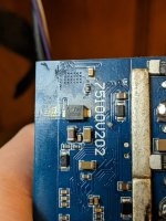
I tried it at more modest 94V in series connection 12+72v. It ran while on stand. I connected and discontented a few times. At first i mixed uo polarity a few times while connecting but it survived it. But the problem is it didn't survived the voltage. It would pop everytime i reconnected thereafter. I saw two cracked mosfets. I replaced them but probably did something wrot, and it blew with smoke on the same 2 mosfets and resistor at the back. So i tried with remaining mosfets it was working but turning off after motor would start spinning. And after i connected 94v other group of fets poped as well i think. Also internal voltage chip doesn't report seeing more than 91v. So i don't know how it can run at this voltage, it cannot. So what do i need to change for it to take 100v? Can someone check again as well on own controller, i suspect mine already had damaged 2 fets, due to lower intial power; i don't know why. Btw it can fail by itself, previous did. Just turn on duty cycle control and it will.
 
Extreemator said:
At first i mixed uo polarity a few times while connecting but it survived it.
Note that "surviving" and "being undamaged" are not really the same thing. It's easily possible to seriously damage components by reversing polarity on the main battery contacts of any controller (unless it has a built in diode to protect against this, and that would probably be a somewhat large part, as it must handle the entire current of the whole system, with a voltage drop across it the entire time it's running normally, creating a power loss across it that wastes a lot of power as heat. (for instance, a 100A battery current, assuming a 0.7v diode drop (could be less) is 0.7 x 100A = 70W, which is as much as a powerful soldering iron used for desoldering FETs/etc from controllers, or soldering up heavy-gauge wiring, etc. ).
 
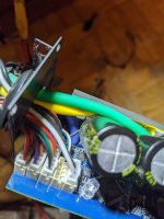
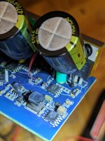
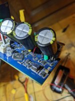
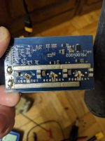
Yes. But how to increase the voltage a bit more safely and if enyone could test it too. Because i don't see affordable alternatives to it as well for high voltage. Here the pcb pictures

[spolier]
PXL_20230103_083100311.MP.jpgPXL_20230103_083240293.jpgPXL_20230103_083203867.jpgPXL_20230102_101217195.jpgPXL_20230103_082159381.jpgPXL_20230103_052106922.jpg[
[/spolier]
 
If you really need higher voltage, I would recommend looking at some of the VESC-based controller threads here on ES; you'd probably have to build the controller based on the thread info, if the developer doesn't sell them themselves. (the flipsky itself is based on a developer's version from ES, for instance, but not sold by the developer).

You mgiht be able to use the info from the higher-voltage version threads to modify your own for that higher voltage, or just replace the power stage of the controller you have with a higher voltage one.
 
Sorry i am not that advanced. I just need a plain hint, if someone has an idea looking at pcb. I wrote to flipsky from which probably won't get a reply. Have to also message the author
 
Extreemator said:
Sorry i am not that advanced. I just need a plain hint, if someone has an idea looking at pcb. I wrote to flipsky from which probably won't get a reply. Have to also message the author

I have one of these 75100, this controller is pretty much useless as it heats up extremely fast.
I don't plan on riding this in the rain, so I am planning on cutting the case and adding a finned heat sink and possibly a little fan on the other end.
 
It's winter now, i haven't had this problem it's not bad, but i just neeeeed more voltage I would pay for it. Although I recently added heatsink recently.
 
Back
Top