Mihai_F
100 W
- Joined
- Oct 11, 2021
- Messages
- 173
hello to all,
I have studied FOC motor control for a good while now, i understanded most of it. If i remember well you have done you own FOC code, so i have some questions about FOC algorithms to clear things out.
So far i understand and made (code) the following: clark transform from Ia, Ib, Ic to alpha and beta, then park transform to d and q, here are 2 formulas one for d aligned with alpha and one for q aligned with alpha, i used q aligned with alpha in order to have a positive q (the other one gives a negative q), then a simple command for d and q no PID yet, then inverse park to get alpha and beta from commanded d and q, then find the theta angle and modulation index from alpha and beta, then from here i used some code i found on github for SVPWM dutycycles, wich i kinda get what it does but not completely.
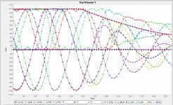
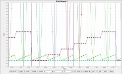
So basically i run this code in STM32F401(black pill) to simulate FOC and i produce artificially 3 sines 120 deg apart, at ~1Hz, and watch all computed FOC variables on var viewer of stm studio, i can change the q and that changes the SVPWM, plus i give feedback to my artificial sines to be more real situation/simulation.
The question are:
1. The theta angle (rotor angle) calculated from atan2(beta, alpha), can be used in sensorless/encoderless FOC algoritm, will it work?, is that the right way of doing FOC?
2. Why is SVPWM out of phase 180deg from initial input sines U V W, in the screenshot?, i do not think that is right...
3. I will use hall sensors only for startup, should i use them to find the theta angle and sector from them after startup on the runn?
4. I plan to use STM32F407ZG (168Mhz) and 3 hall current sensors on phases, and have Tim1 channel 1,2,3 center aligned complemetary pwm generation (mode1) and channel 4 output compare to trigger ADC in the center of the PWM pulse, ADC1 injected ch1, ch2 and ch3 sequential order , is this the "correct/good" way to do things?
5. If i understand well, if ARR is 1000 and q comand is 0 then all 3 duty clycles are at 500, all fets swithcing all outputs fom high to low (comlementary PWM half on, half off of the time), in that case the motor is i brake condition (shorting the phases together), how to achieve motor coasting and not braking when q comand is 0, like when you go down hill with throttle at 0 , coasting and not braking.
here are the screen shots:


Code:
//FOC simulation

volatile int PermuataionMatrix[6][3] =
{
    { 1, 2, 0 },
    { 3, 1, 0 },
    { 0, 1, 2 },
    { 0, 3, 1 },
    { 2, 0, 1 },
    { 1, 0, 3 }
};

volatile int UDC=1000;

            // generate step for sine
            sin_step = sin_step + 0.001;
            if(sin_step >(2*M_PI)) sin_step = 0.0;

            //dutycyle= sin(sin_step);

            //Generate 3 sine waves 120deg apart
            dutycyle_U= sin(sin_step)*1000*amplitude_comand;
            dutycyle_V= sin(sin_step-(2*M_PI)/3)*1000*amplitude_comand;
            dutycyle_W= sin(sin_step+(2*M_PI)/3)*1000*amplitude_comand;

            //Clark transform
            //alpha= (2.0f/3.0f)*dutycyle_U - (1.0f/3.0f)*(dutycyle_V - dutycyle_W);
            alpha= 0.666666*(dutycyle_U - 0.5*dutycyle_V - 0.5*dutycyle_W);
            //beta= (2.0f/sqrt(3))*(dutycyle_V - dutycyle_W);
            beta= 0.666666*(0.866025*dutycyle_V - 0.866025*dutycyle_W);


            //find theta angle
            theta= atan2f(beta,alpha);

            //Park transform q axis aligned to alpha
            d_axis= alpha*sin(theta)- beta*cos(theta);
            q_axis= alpha*cos(theta)+ beta*sin(theta);

            //Command
            amplitude_comand= FilteredReadADC12bit/4095;    //get amplitude
            d_axis_new= d_axis;
            q_axis_new= q_axis* amplitude_comand;    // amplitude


            //Inverse Park transform
            V_alpha= -d_axis_new*sin(theta)+ q_axis_new*cos(theta);
            V_beta= d_axis_new*cos(theta)+ q_axis_new*sin(theta);

            //find new theta angle offset by 90deg and modulation index
            theta_sh= atan2f(V_beta,V_alpha)+M_PI;
            mod_index= hypotf(V_beta,V_alpha);

            //Calculate duty cycles code from github

                //Max_mod_ix= UDC * (1.0f/sqrtf(3.0f));
                Max_mod_ix= UDC * 0.577;

                if(mod_index > Max_mod_ix) mod_index = Max_mod_ix;
                Scaled_mod_ix= mod_index / Max_mod_ix;

                Sector= theta_sh * (1/(M_PI/3));
                angle= theta_sh - (M_PI/3) * Sector;

                T1= Scaled_mod_ix*(sin(M_PI/3- angle));
                T2= Scaled_mod_ix*(sin(angle));

                Ti[0] = (1 - T1 - T2)*0.5;
                Ti[1] = T1 + T2 + Ti[0];
                Ti[2] = T2 + Ti[0];
                Ti[3] = T1 + Ti[0];

                CCRA = 1000 * Ti[PermuataionMatrix[Sector][0]];
                CCRB = 1000 * Ti[PermuataionMatrix[Sector][1]];
                CCRC = 1000 * Ti[PermuataionMatrix[Sector][2]];
