For Sabvoton sine wave motor controller users

GordonF said:
Help with SVMC 72150 Controller Wiring please.
I recently purchased a controller (NCyclebike, China) but it is wired differently to anything I've seen from Mqcon / Sabvoton. The controller is pre-wired with a "waterproof" loom (for the functions of speed throttle, brake lever switches & TFT display). Fair enough, but separately there is also a male 3-pin connector (black, green, yellow) and a female 3-pin connector (brown, green, yellow). I have asked the vendor repeatedly what these wires are for but they won't or can't tell me (absolutely shocking, but I've reached a dead-end..!).
I'm told that the connectors should be separated for normal running, but joined for programming.
Does anyone know how those connectors correspond to the SVMC standard wiring diagram...?
I have the same controller it can be ordered with or without the waterproof plugs I ordered without but those wires are the same.

Those wires are for the Bluetooth programming when running the TFT color display. You must disconnect them to use the Bluetooth programmer and reconnect them when you go back to using the TFT color display.

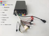
Attached a picture and number diagram with the corresponding connectors
 

Attachments

  • IMG-20200505-WA0006.jpg
    IMG-20200505-WA0006.jpg
    72.8 KB · Views: 3,024
Hello. I have 96120 sabvoton controller with 5000w motor. Can i use cycle analyst or some other display to check speed, current and so on?
 
alex9 said:
Hello. I have 96120 sabvoton controller with 5000w motor. Can i use cycle analyst or some other display to check speed, current and so on?

yes you can with CA3, that is how my new build is set up.
 
zzrider said:
Hello,
I´m using Sabvoton 48V 100A (new gen.) controller for my e-scooter project. Now I have connected controller to my bike but there seems to be one problem I can not overcome:

Acceleration works fine but just after releasing throttle (to decelerate), overcurrent error is flagged (ID_8) and controller requires restart. Also, right after releasing accelerator, a punch from motor can be heared, sounds like motor attempts to make a brake. If i don´t remove my hand from throttle on full speed, this does not occur. What could be the cause of this and how could it be avoided?

I am using 48V battery and BLDC motor with reducer transfering power to the rear wheel via chain and sprockets.
Also I do not exactly understand why hall angle test gives out different hall angle values. For example, testing with currents 15-30A I got hall angles from 4-8 deg. When I physically measure hall sensor angle from my engine PCB I get 17 degrees. Why does this value vary so much and which result should be trusted?
I have attached several pictures of my initial setup.
Thanks!


Hi Everybody, Martin from Germany here.
i have an equal Problem like in the Post.

But my Motor speeds up and then get "stucked" with fault Over Current. but there is only the Motor Spinning....
There should be not much current on the motor....

Can the Max Erpm of the motor be a reason to react in this way??
If got on AlienPower 12090 - (28Magnets/ 14 Pairs) 30000erpm/14 Pairs = 2142 rpm.

When its go higher, the motor seemd to cut off.....
 
I also try to change th KP - in the APP

the motor runs with KP - 0, until KP 250, over 250 the Motor makes very much noise.
between 0 and 250 its sometimes more or less noise.... But i think it maks any difference...
 
heini320 said:
Can the Max Erpm of the motor be a reason to react in this way??
If got on AlienPower 12090 - (28Magnets/ 14 Pairs) 30000erpm/14 Pairs = 2142 rpm.

When its go higher, the motor seemd to cut off.....

I think it has to do with this, but I'm not entirely sure because it happens only when releasing the throttle while already at top speed. In my case, it happens to lock the wheel, which is slightly dangerous when you're running at 125+kph. I noticed that if I slightly lower the flux weakening, then I reach only 120kph and I don't have the problem. So that's how I fixed it.
Funny thing is that it is very hot these days, so the battery voltage got up by a tiny bit, giving me a tad more top speed... So it did happen again because I got over 125 briefly
 
Thnx for all the info above; very useful.

I bought a svmc72150 without display, not realizing that it also does not have a pedal Assist signal cable. As I will be using the sabvoton for an ebike, I really would like to Be able to use a pas sensor.

My questions to you:
1: is it possible to add a pas signal cable, or are the controllers with and without tft really different?
2: do I need different firmware?
3: where do the pas cables connect to the pcb; does anybody know the pin out? And additionally for setting the pas level?
4: can I connect cycle analist v3 to this controller and implement Pas using CAv3 (if the other 3 options are not possible)?

Any help would be highly appreciated! It is a nice controller, but the lack of pas is really a no go for me. So otherwise I would need to sell it again.
 
hello, I have a 72100 MQCON without reverse wire.. would be possible implement it?
 
I have the SVMC72100 and have been playing around with it for a bit and have it programmed for the most part the way i would like . But top speed does not seem quite fast enough, (52v 32ah) source. On a previous controller an ERT 12fet i was hitting way more speed. Flux or not normal full throttle is low, guessing 35-40mph top, i should be able to hit a clean 50mph....
So what settings shuld i mess with program wise."Internal speed limit? mid, Low?" The "Speed Limit mode" is set to No Limit. My throttle max voltage is set to 4.4v and mid at 2.5v. Now I only have a single blue wire for "e Brake" that plugs into itself for motor cut or re gen, I dont think i have a "Boost" wire on my controller but maybe that would be gtreat to activate. Over all the top speed is less than i was hoping for ...
 
Just hooked up my 7280 & UKC-1 and I have several questions. Support from Hallomotor / Risun has been underwhelming eg they told me there is software for my Mac, then sent an iPhone link. Fortunately that does work on my phone via bluetooth, but I think the PC app has more options. I don't have a PC :(

Its currently running at 48V and hooked up to a Voliamart 1000W hub, might upgrade if it fries ;)

1. Power - I have set DC current and Boost Current to 40A. Yet sometimes I see almost 3000W on the controller. I wanted to limit it to 2000W initially. 48x40= ~2000W. Is there another setting to set a hard limit?

2. Maximum power jumps all over the place: on settings 2-5 at full throttle sometimes it stops at ~1200W. Sometimes just under 2000W. Sometimes just under 3000W. With the same settings. I'm not currently using PAS. Any idea why?

3. Speed readout - the digital speedo shows ~25kmh when I'm doing ~15kmh. Wheel size is set to 26" on the UKC-1. Is there another setting to correct this?

4. Voltage - the claimed maximum for the 7280 is 95V: will I get away with adding a 36V pack in series to the 48V pack? This should be *just* under 95V with both batteries fully charged. Will the UKC-1 display and controller cope? I notice the display's maximum voltage setting is 72V

5. Temperature - I wanted to set limits for motor temperature in the controller, but my 7280 is missing the temperature sensor wire in the Hall connector. The listing said the controller had a max temp setting, but it turns out thats only for controller temperatures :( Is there a way of adding a motor temperature sensor wire to the 7280? I've seen instructions on adding one to the motor.

Lots of questions I know, I couldn't find answers in search. I've learnt a lot reading other threads on here :)
 
Is there a manual for Sabvoton controller that will tell which temperature sensor will support. I believe not every sensor will be recognized by Sabvoton...

Also was trying to search on the forum but could not find the proper place where temperature sensors can be discussed - "which better, worse, etc."

Just bought QS 1200w motor from SiAECOSYS. In the description says "Thermic probe - KTY83/122", but is not there because hall sensors come with 5 wires only, without white wire that can be sending info from sensor to controller...

Was speaking to Summer from SiAECOSYS/QS Motor, and he says that in 1200w motor is no space for temp sensor... Is that joke or it really in that model everything that "compact" there is no space?
 
There's plenty of space for the sensor; it can go anywhere in the motor (but is usually right at or under a winding so it reads the worst and fastest peak temperatures to help prevent winding damage).

The problem is they still use a drilled-out axle hole for the wires to get out of the case, so there is only so much space for the wires. If they use more wires, then they have to use thinner ones, and for whatever reason they likely choose to use thicker signal wires than they need to. (this is the case with the QS205 I have here). So there wasnt' room for them to fit that one extra wire.

If you're willing to open up the motor and add a sensor, then you can also replace the signal wires with thinner ones, you can add that wire in there, or even a completely independent pair of shielded wires (better for signal quality) to that sensor, and also use separately shielded wires for the hall signals.

If it fits in the axle hole, you could replace the entire motor cable with the sold-by-the-meter cable that Grin Tech carries, which includes seven signal wires plus power/ground wires, plus three phase wires:
https://ebikes.ca/shop/electric-bicycle-parts/wiring/grinmotorcable.html
Custom high strand count flexible motor phase and signal cable from Grin Technologies, 9.0 mm Jacket Diameter. Includes 3 cores of 12 gauge teflon insulated wire for motor phase power, and a shielded 7 conductor 24g wire bundle for hall signals and thermistor.

It's pretty good quality cable from the length I have here, though the thick cable jacket may not allow it to fit without some modification in small axle holes.


If they would just go with a system that uses a much larger ID bearing, and a thick spacer between the bearing and the axle, (or a much larger diameter axle shoulder at this point), then there would be plenty of room for any wires that were needed, and much larger phase wires as well, and also separating each type of wire (phase vs signals vs type of signals) so there can be no interference from high currents in the phase wires into the halls or other signal wires. Almost no motors do anything like this.

If they did this by using the larger-axle-shoulder on one side, and a drilled spacer on the other (or a notched shoulder) it would *also* let them affix a torque arm directly to that shoulder (as only a few motors do), and not have to use flatted axles to transfer torque from motor to frame (whcih is a terrible idea for multiple reasons and breaks axles and frames).
 
Thanks for quick reply...
Yes, it was strange for me too, that they said that is no space for a tiny sensor...
I did have little experience of replacing original signal wire and phase wires. Dop0 use 1000w motor a got problem with overheating phase wires (especially in the summer), so I replaced original phase wires with double each phase Silicone 200°C  16AWG- then when they're coming out the motor connected using XT150 to Heat Resistant 300°C Glass Fibre 9AWG.

https://youtu.be/WPlgqfhsCCY

And that is how much space in the axle of my new QS 1200w motor - its plenty space for "upgrade phase wires" and all 6 signal wires...

https://youtu.be/WPlgqfhsCCY
 
serginho007 said:
so I replaced original phase wires with double each phase Silicone 200°C  16AWG- then when they're coming out the motor connected using XT150 to Heat Resistant 300°C Glass Fibre 9AWG.
16awg? That's pretty thin--I don't think even my old 9C "500w" hubmotors used less than 14, from the factory, but it's been years so I don't know for sure. The higher gauge wire will help carry the heat away, but if you can fit bigger wire, it'll help reduce the heat generated (if phase currents are high enough to generate significant heat in the wires themselves anyway, which they may not be).


The Grin Tech cable uses 12awg, so will handle plenty of current for the average ebike hubmotor application. (even for my heavy cargo bikes/trikes, so far, on the ex-Stromer motor I use on the right side of SB Cruiser, using this cable).


BTW, your videos are private, so can't be seen by anyone but you. ;)

If you take pictures and attach them to the post itself, then anyone that can see the post can see the pics.
 
Yes, they are 16AWG but dont forget they two wires for each phase...

"Unprivated" :lol: videos.

That's the visual difference between original 1200w motor wire and my silicone 16AWG.


And that wire I will be installing in the new motor which is this (13AWG (OD 2.8mm) but actual OD is 2.6mm)

https://www.aliexpress.com/item/4000567194953.html?spm=a2g0s.9042311.0.0.27424c4d0o8NTD


amberwolf - Thank you for the link to Grin phase wires... Do you know what is the length of that? In the description could not find that :shock: -Sorry missed... Price per mitre!!! Will get maybe 5 mitres for stock.
 
Most likely it would be compatible with any sensor that has the same properties as that KTY83 sensor, assuming that the controller would have been compatible with the motors that do have that sensor in them (which you might have to find out from the seller). Meaning, the same base resistance at "zero", and the same amount of change of resistance over the same temperature range.

If the controller has a calibration setting in it's setup program, then you could use that to make it match whatever sensor you do get, depending on how much calibration it can do and/or what settings it has available.

If it doesnt' have any way to change it, then you'd need to use the same kind of sensor, or one that matches it's properties. AFAIK the KTY83 is discontinued but you may be able to find some around the web. This should be it's specs:
https://www.nxp.com/documents/data_sheet/KTY83_SER.pdf?
and this is a basic look around for places that might have or at least reference it (I have not looked at any of the links):
https://www.google.com/search?q=kty83+temperature+sensor&oe=utf-8


serginho007 said:
Yes, they are 16AWG but dont forget they two wires for each phase...
Ah, somehow I missed that part. :oops:


And that wire I will be installing in the new motor which is this (13AWG (OD 2.8mm) but actual OD is 2.6mm)

https://www.aliexpress.com/item/4000567194953.html?spm=a2g0s.9042311.0.0.27424c4d0o8NTD
As long as that is actually good teflon insulation, it will probably work ok. But if it is like other transparent-insulation "speaker wire" I have used and seen in various things, it may be very very soft and easily damaged by sustained pressure on it (it deforms, or flows, away from the pressing item, eventually letting the item touch the conductor inside). If wires are twisted around each other, then any pulling force on any of the wires puts pressure on the casing and the flowing begins. Or if the wires press against the edge of the hole where they go into or out of the axle.... Etc.

It can take a long time (weeks, months, or more) for this to become a problem, but it does happen with soft-insulation wiring of various kinds (including teflon / ptfe), and happens faster the warmer things are.
 
amberwolf said:
Most likely it wouldbe compatible with any sensor that has the same properties as that KTY83sensor, assuming that the controller would have been compatible with the motorsthat do have that sensor in them (which you might have to find out from theseller).  Meaning, the same baseresistance at "zero", and the same amount of change of resistanceover the same temperature range.   If the controller hasa calibration setting in it's setup program, then you could use that to make itmatch whatever sensor you do get, depending on how much calibration it can doand/or what settings it has available.   If it doesnt' have anyway to change it, then you'd need to use the same kind of sensor, or one thatmatches it's properties.  AFAIK the KTY83is discontinued but you may be able to find some around the web.   This should be it's specs:https://www.nxp.com/documents/data_sheet/KTY83_SER.pdf?and this is a basiclook around for places that might have or at least reference it (I have notlooked at any of the links):https://www.google.com/search?q=kty83+temperature+sensor&oe=utf-8
Thank you for your help. Will order an appropriate sensor first, then will play with the settings on the controller which ordered today (should come by end next month)
   
amberwolf said:
As long as that isactually good teflon insulation, it will probably work ok.
Bought those wires by recommendation of another user (from russian ebike forum) that has them installed in his bike for a long time... -  so that seller already verified and selling a good product.
  a lot of work will be done to make that QS motor "ready to ride".

1. Installing new phase wires with adding new signal for sensor
2. Installing a sensor
3. Finish with weatherproofing with Red insulating varnish EL 601

Then we will see how long it will last...
 
 
Kylowrench said:
Just hooked up my 7280 & UKC-1 and I have several questions. Support from Hallomotor / Risun has been underwhelming eg they told me there is software for my Mac, then sent an iPhone link. Fortunately that does work on my phone via bluetooth, but I think the PC app has more options. I don't have a PC :(

Its currently running at 48V and hooked up to a Voliamart 1000W hub, might upgrade if it fries ;)

1. Power - I have set DC current and Boost Current to 40A. Yet sometimes I see almost 3000W on the controller. I wanted to limit it to 2000W initially. 48x40= ~2000W. Is there another setting to set a hard limit?

2. Maximum power jumps all over the place: on settings 2-5 at full throttle sometimes it stops at ~1200W. Sometimes just under 2000W. Sometimes just under 3000W. With the same settings. I'm not currently using PAS. Any idea why?

3. Speed readout - the digital speedo shows ~25kmh when I'm doing ~15kmh. Wheel size is set to 26" on the UKC-1. Is there another setting to correct this?

4. Voltage - the claimed maximum for the 7280 is 95V: will I get away with adding a 36V pack in series to the 48V pack? This should be *just* under 95V with both batteries fully charged. Will the UKC-1 display and controller cope? I notice the display's maximum voltage setting is 72V

5. Temperature - I wanted to set limits for motor temperature in the controller, but my 7280 is missing the temperature sensor wire in the Hall connector. The listing said the controller had a max temp setting, but it turns out thats only for controller temperatures :( Is there a way of adding a motor temperature sensor wire to the 7280? I've seen instructions on adding one to the motor.

Lots of questions I know, I couldn't find answers in search. I've learnt a lot reading other threads on here :)
I asked Hallomotor, and they have been of some help

1. please set rated phase current to 60A, then the power is 48V 2000W. Setting DC current and Boost Current is useless
2.I don’t understand what you mean, power is related to current. Do you mean that under the same current and the same lever setting, full throttle sometimes the power is different? They later said “it varies” lol
3.Please set the correct value of "motor poles pair" in the APP - not sure what to set this to for my Voliamart 1000W rear hub
4.No
5.No
 
Kylowrench said:
1. please set rated phase current to 60A, then the power is 48V 2000W. Setting DC current and Boost Current is useless
2.I don’t understand what you mean, power is related to current. Do you mean that under the same current and the same lever setting, full throttle sometimes the power is different? They later said “it varies” lol

What they apparently mean is that the controller software is poorly written, and the DC Current and Boost Current settings don't work correctly or at all, etc.

So the setting they seem to think does work is the phase current, which si the current not at the gbattery wires but at the motor phase wires, which is usualy higher by some ratio than the battery current. Whether this will really limit you to a strict 2000w, I can't say as I don't know the specifics of how that controller interprets all it's settings and how they all interact in actual operation.


3.Please set the correct value of "motor poles pair" in the APP - not sure what to set this to for my Voliamart 1000W rear hub
It's probably 23. If you put your voltmeter to 20DCVolts, and it's black lead on battery negative, and its' red lead on any of the hall signal wires, then carefully rotate the wheel one rotation, watching the display the whole time. Count the number of times it changes from around 0-1v to around 4-5v. That's the #poles (pairs).
 
amberwolf said:
Kylowrench said:
1. please set rated phase current to 60A, then the power is 48V 2000W. Setting DC current and Boost Current is useless
2.I don’t understand what you mean, power is related to current. Do you mean that under the same current and the same lever setting, full throttle sometimes the power is different? They later said “it varies” lol

What they apparently mean is that the controller software is poorly written, and the DC Current and Boost Current settings don't work correctly or at all, etc.

So the setting they seem to think does work is the phase current, which si the current not at the gbattery wires but at the motor phase wires, which is usualy higher by some ratio than the battery current. Whether this will really limit you to a strict 2000w, I can't say as I don't know the specifics of how that controller interprets all it's settings and how they all interact in actual operation.


3.Please set the correct value of "motor poles pair" in the APP - not sure what to set this to for my Voliamart 1000W rear hub
It's probably 23. If you put your voltmeter to 20DCVolts, and it's black lead on battery negative, and its' red lead on any of the hall signal wires, then carefully rotate the wheel one rotation, watching the display the whole time. Count the number of times it changes from around 0-1v to around 4-5v. That's the #poles (pairs).

Thanks 23 poles is spot on - the displayed speed matches my GPS phone app

Weirdly the other settings all do *something* but not in a way that I understand. If I increased the DC & Boost settings it definitely allows for more power. As does changing phase current.
 
My Sabvoton 80A arrived this week and first thing I realized that it can't read motor temperature from the box!!! I was thinking all Sabvoton controllers can do that from the box...

It's possible to add that 6th white wire from the controller that will read motor temperature? Someone already did that with Sabvoton controllers?

Also, interesting where you Sabvoton users fit controller... Inside in the frame or outside? Its big and taking so much space inside. But if fix outside then need 3d print some kind of cover at least to protect phase and power wires on the controller side from the water... Ant ideas pictures, maybe.

Thank you for any help.
 
serginho007 said:
My Sabvoton 80A arrived this week and first thing I realized that it can't read motor temperature from the box!!! I was thinking all Sabvoton controllers can do that from the box...

It's possible to add that 6th white wire from the controller that will read motor temperature? Someone already did that with Sabvoton controllers?

Also, interesting where you Sabvoton users fit controller... Inside in the frame or outside? Its big and taking so much space inside. But if fix outside then need 3d print some kind of cover at least to protect phase and power wires on the controller side from the water... Ant ideas pictures, maybe.

Thank you for any help.
I had the same issue - Risun / Hallo said you can't add a temperature sensor. If anyone figures out a way I'd like to know. I'm in the process of adding an extra screen instead...

My controller is in a toolbox on the rear rack. Not sure its the best solution for cooling, but it is neat
 
Kylowrench said:
My controller is in a toolbox on the rear rack. Not sure its the best solution for cooling, but it is neat

Tool box maybe a solution, but I'll still try to mount underneath of the frame because in tool box I would need to extend all wires about 500 mm from controller, so trying to avoid that and prefer instead water/mud proof phase section with something...
 

Attachments

  • Frame.jpg
    Frame.jpg
    229.7 KB · Views: 1,698
Can you give us a breakdown for the sabvoton 72200 controller. I'm guessing this guide was written before the 200a version was available.

I was constantly throwing up the 02h error code at first before lowering all the figures that control the output from controller to motor. (Phase and DC current)

I have yet to play with flux weakening and regen braking.

I am running the controller on "boost" as the mode setting. I do not have a boost button or 3 speed control.

CURRENT SETUP

I have a 21s2p battery using the EIG pouch cells
Ant 180a/450a peak bms
Sabvoton 72200 controller
Qs273 hub motor

CURRENT SETTINGS

Lack voltage (V) - 60
Current-limiting voltage (V) - 65
Over voltage (V) - 88
DC current (A) - 150
Boost current (A) - 150
Rated phase current (A) - 180
Max phase current (A) - 200
Protective phase current (A) - 300

The goal is maximum power, it's not too bad performance on the above settings but I need advice on how to get the most out of my set up

Thanks
Jack
 
Back
Top