
You are using an out of date browser. It may not display this or other websites correctly.
You should upgrade or use an alternative browser.
You should upgrade or use an alternative browser.
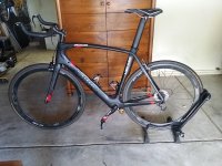
Friction Drive New Kepler carbon build
- Thread starter Kepler
- Start date
Kepler
10 MW
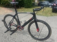
That is a good question. With the last carbon build I did it was built as a primary every day commuter and spent much of its time on less then ideal bike paths. It soon became apparent even the unsprung weight of a small hub motor in a carbon frame and on narrow tires made for a less than ideal combination for general bike path commuting and hence the change to a more complaint 2" tire was made.
This bike is not being built for that purpose. I have my BBS02 full suspension 2" tired 29'er for day to day commuting duties. A combination in my opinion that is hard to beat.
This new bike is being built as a road bike and will rarely see bike path duties. It will have no additional unsprung weight however I have gone to 28mm tire that i run at 80psi to give the bike a little more compliance and to give the friction drive a little more to work with.
Mikebergy
1 W
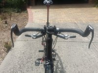
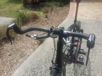
It is an interesting handlebar setup you have there. I've not seen those little extra bars you have your shifters on before, what are those?
Kepler
10 MW
Those are a Kepler Special 
I really wanted to stick with the Bullhorn bars with the TT style bar end brakes but there were no commercial shifter options that made gear shifting accessible while still in your normal riding position. So I ended up finding a cheap TT bar combo, removed the forearm pads, and cut down the front bars to suit my shifter layout. More then pleased with the result. Also bar end shifters and bar end TT aero brakes are much cheaper than traditional drop bar brake shifter combos.

http://www.cyclingdeal.com.au/buy/pz-racing-triathlon-time-trials-tt-bike-bicycle-ha/TTH-05
I really wanted to stick with the Bullhorn bars with the TT style bar end brakes but there were no commercial shifter options that made gear shifting accessible while still in your normal riding position. So I ended up finding a cheap TT bar combo, removed the forearm pads, and cut down the front bars to suit my shifter layout. More then pleased with the result. Also bar end shifters and bar end TT aero brakes are much cheaper than traditional drop bar brake shifter combos.
http://www.cyclingdeal.com.au/buy/pz-racing-triathlon-time-trials-tt-bike-bicycle-ha/TTH-05
Attachments
oatnet
1 MW
Oh Kepler, I like where this is going.
-JD
-JD
Like the bike John. ")
If you haven't named it already I can think of a great name...The Impaler
Cheers
If you haven't named it already I can think of a great name...The Impaler
Cheers
Kepler
10 MW
Thanks all for the kind words and support.
CD, interesting name suggestion.
So clocked up 120 km on the bike this weekend. Very happy with the way it rides and looking forward to stage 2 of the build.
CD, interesting name suggestion.
So clocked up 120 km on the bike this weekend. Very happy with the way it rides and looking forward to stage 2 of the build.
Kepler
10 MW
Yep, that would have been exactly what I was looking for. Thanks for the link.
Kepler
10 MW
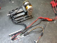
For the electric side of this build, I am working on the controller and battery layout first.
With most outrunner RC motor friction drive setups, an RC style speed controller is also used. With this build I am using a traditional ebike controller so I can utilize the inbuilt current limiting features plus various other features that are a standard part of an ebike controller.
The controller is KU65 and I have selected this controller because they are super cheap and also there is a great blog on how to modify these controllers. http://www.avdweb.nl/solar-bike/electronics/ku63-motor-controller.html
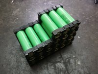
However there are some major limitations when using an ebike controller with an RC motor, the main one being the maximum electrical RPM the ebike controller can output. With this in mind, I needed to match my pack voltage and motor kV to the maximum electrical RPM that the controller could stably supply. Using 200kV outrunner, I found that the output voltage of a 7S pack 18650 under load was a good fit.
Now that I had settled on a pack voltage, I now needed to make some modifications to the controller so that the low voltage cut out suited the pack chemistry. Getting the cutout voltage correct was important step on this build due to the pack being quite small and compact with no BMS fitted. Subsequently I am relying on the controller low voltage cutout to protect the battery.
A 5K pot has been installed on the throttle circuit to adjust the controller output. The pot will be mounted under the seat out of view. Drive activation is via the controller's brake input. this will be connected to the normally closed side of a microswitch which will inturn open circuit when the motor is pivoted against the tire.
Being a sensorless controller, they can have some issues starting an outrunner RC motor. When this happens, it puts a lot of strain on the controller and can blow the controller if the motor isn't given a helping flick to get it started. With this in mind, this design will pull the motor onto the tire first so it is already spinning before the microswitch activates the drive through the brake circuit.
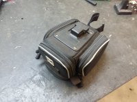
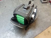
I am still in two minds on where I am going to mount the controller and batteries on this bike. The 2 choices are in a small seat post bag or inside a custom water bottle or water bottles. I really like the water bottle path but fitting an ebike controller into a water battle doesn't leave much room for batteries. Best i could do is a 7S 2P setup which would be 130 Whrs.
Option 2 is mounting everything inside a small seatpost bag. This simplifies the build quite a bit and allows me to carry a 7S3P pack which provides about 200 Whrs. The frame has an opening under the bottom bracket to get my motor cables through together with the microswitch connection. I would however need to drill a hole in the carbon seat tube to run the wires through. I can live with that as this hole wouldn't affect the strength or structure of the bike, only the seatpost which could easily be replaced if needed.
Although the seatpost bag solution is the best practically, i am not sure if I will be happy with the aesthetics of this setup. The plan is to give this a go first and see how I go for range. If I find I am not using all the battery, i will consider going back to the water bottle solution.
Progress photos as the project stands.
With most outrunner RC motor friction drive setups, an RC style speed controller is also used. With this build I am using a traditional ebike controller so I can utilize the inbuilt current limiting features plus various other features that are a standard part of an ebike controller.
The controller is KU65 and I have selected this controller because they are super cheap and also there is a great blog on how to modify these controllers. http://www.avdweb.nl/solar-bike/electronics/ku63-motor-controller.html
However there are some major limitations when using an ebike controller with an RC motor, the main one being the maximum electrical RPM the ebike controller can output. With this in mind, I needed to match my pack voltage and motor kV to the maximum electrical RPM that the controller could stably supply. Using 200kV outrunner, I found that the output voltage of a 7S pack 18650 under load was a good fit.
Now that I had settled on a pack voltage, I now needed to make some modifications to the controller so that the low voltage cut out suited the pack chemistry. Getting the cutout voltage correct was important step on this build due to the pack being quite small and compact with no BMS fitted. Subsequently I am relying on the controller low voltage cutout to protect the battery.
A 5K pot has been installed on the throttle circuit to adjust the controller output. The pot will be mounted under the seat out of view. Drive activation is via the controller's brake input. this will be connected to the normally closed side of a microswitch which will inturn open circuit when the motor is pivoted against the tire.
Being a sensorless controller, they can have some issues starting an outrunner RC motor. When this happens, it puts a lot of strain on the controller and can blow the controller if the motor isn't given a helping flick to get it started. With this in mind, this design will pull the motor onto the tire first so it is already spinning before the microswitch activates the drive through the brake circuit.
I am still in two minds on where I am going to mount the controller and batteries on this bike. The 2 choices are in a small seat post bag or inside a custom water bottle or water bottles. I really like the water bottle path but fitting an ebike controller into a water battle doesn't leave much room for batteries. Best i could do is a 7S 2P setup which would be 130 Whrs.
Option 2 is mounting everything inside a small seatpost bag. This simplifies the build quite a bit and allows me to carry a 7S3P pack which provides about 200 Whrs. The frame has an opening under the bottom bracket to get my motor cables through together with the microswitch connection. I would however need to drill a hole in the carbon seat tube to run the wires through. I can live with that as this hole wouldn't affect the strength or structure of the bike, only the seatpost which could easily be replaced if needed.
Although the seatpost bag solution is the best practically, i am not sure if I will be happy with the aesthetics of this setup. The plan is to give this a go first and see how I go for range. If I find I am not using all the battery, i will consider going back to the water bottle solution.
Progress photos as the project stands.
Attachments
tomjasz
1 GW
I'm becoming mare and more enamored by little packs. Everyone wants big an powerful, but having a small pack that meets the basic needs of a rider sure are stealthy. Cheap to build too. I scored a couple of cheap BMS from a good builder. Only 30A capable but for $12! Sam's battery supplier has them. Pretty much the same as Nobu has been using.
Looking good John.
Just be careful with that seatpost bag...I've had the exact same bag for about 18 months on my Fighter and the other day, without much force, the plastic buckle receiver on the bag cracked and were it not for the seat post velcro it would have fallen off.
With just my tools and a first aid kit in the bag, I don't think it would weigh more than your batteries and controller. I've 'repaired' mine with zip ties strung under the clip bracket and so far it's held up fine.
You may want to add a few strong zip ties to yours as an insurance policy.
Cheers
Kepler
10 MW
Thanks CD. Good point on the bag strength. Did yours fail with off road duties or just commuting duties?
fesanand
10 W
- Joined
- Jun 1, 2014
- Messages
- 98
In case it helps as an inspiration...
My solution for that is a cheap set of backpack clips + backpack nylon strips.
Currently my saddlebag is 2.2kg and never had a problem reliability.
In the picture the red part is a short nylon strip sewed to the saddle rails + its female clips. When saddle bag is unmounted those two clips remain in the saddle, but they're quite stealthy.
The green part is a long nylon strip which goes inside and outside the saddle bag like a ring, sewed. Plus its male clips.
No worries.Kepler said:Thanks CD. Good point on the bag strength. Did yours fail with off road duties or just commuting duties?
I don't commute on my Fighter any more...copped too much abuse and it was only a matter of time before I got nabbed.
I was just bashing about the backyard when the bag broke. I think I knocked it slightly...can't remember exactly, but I do recall it wasn't a hard hit and was surprised it broke so easily.
I also had mine mounted at more of an angle from horizontal...closer to about 30 degree's so that could have been part of it, although you would think that would make it less likely to break.
My zip ties are holding it fine for now though. It survived my last off-road adventure perfectly in tact.
Cheers
Kepler
10 MW
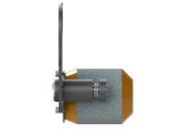
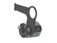
Started fabricating parts for the friction drive. The intent of the design is to keep it as minimalistic as possible and keep the attachment bracket and swingarm mainly hidden behind the chainring. On the non drive side of the bottom bracket, the only thing you see is the motor.
I will paint the end of the motor matt black to help it blend into the frame.
The actual design is still evolving around the constraints of the bike but once completed i will post up some detailed drawings and pictures.
I will paint the end of the motor matt black to help it blend into the frame.
The actual design is still evolving around the constraints of the bike but once completed i will post up some detailed drawings and pictures.
Attachments
Lurkin
100 kW
How much room is there inside the seatpost/seatpost frame area? Could sticks of 18650s be inserted?
I take it the mechanism for engaging/disengaging the drive will be spring loaded and activated via a cable?
I take it the mechanism for engaging/disengaging the drive will be spring loaded and activated via a cable?
Kepler
10 MW
Unfortunately there is no room in the frame to fit batteries. The frame has an aero profile making hard to get a few wires down let alone trying fit batteries inside the frame.
Drive activation will be via the front derailleur shifter and associated shifter cable.
Drive activation will be via the front derailleur shifter and associated shifter cable.
tomjasz
1 GW
Brilliant fellows down there. A seat pack will never give it away!
Kepler
10 MW
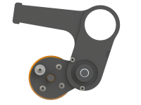
Made some good progress with the drive design. The challenge has been keeping the assembly slim and stiff while only mounting it off one side of the bottom bracket. This will hopefully be achieved by using 1.2mm CroMo steel and using a doubler arrangement to provide the extra rigidity that is required. Being constructed from steel means all the main components can be welded together rather then screwing parts together as with a normal aluminium plate build.
The extended arm on the second plate will be cable tied to the chain stay to help stop the mount twisting when the drive is activated. The coil spring on the shaft will keep the swing arm under tension and away from the tire.
Should have a working prototype ready in the next week or 2.
The extended arm on the second plate will be cable tied to the chain stay to help stop the mount twisting when the drive is activated. The coil spring on the shaft will keep the swing arm under tension and away from the tire.
Should have a working prototype ready in the next week or 2.
Attachments
Lurkin
100 kW
Damn that's sneaky! Nice work John, it will be very tidy especially if painted black. 8)
One of the guys at work is in an identical situation and is very interested in your design. I think it has a lot of appeal! Will you be willing to sell the mounting bracket/kit solely? we have another controller option which could be plug and play (assuming the motor choice is compatible) where all the programming legwork has already been completed.
One of the guys at work is in an identical situation and is very interested in your design. I think it has a lot of appeal! Will you be willing to sell the mounting bracket/kit solely? we have another controller option which could be plug and play (assuming the motor choice is compatible) where all the programming legwork has already been completed.
Kepler
10 MW
Made some good progress today. Finished fabricating and assembling all the main parts. I was concerned that the 1.2mm CroMo would be too springy but reinforcing the the main mounting plate with a doubler has made it plenty stiff enough. Changed the end stop design to welded fixed plates and also simplified the activation cable attachment method.
Mechanically, the drive engages the tire really smoothly using the gear shifter with the micro-switch also activating nicely as the motor is drawn up.
With the minimalistic design, the drive came in at a feather weight 550 grams despite being made from steal opposed to traditionally aluminium. The choice of steal ended up being a real advantage with major components being welded rather then screwed together.
Will hopefully get a run out of the drive tomorrow and do some testing. Once satisfied with the performance, I will pretty it up with some matt black paint.
Attachments
Kepler
10 MW
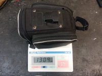
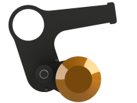
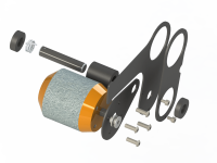
Finished off the drive mechanically and set it up ready to accept some power.
Actually came up a bit lighter than anticipated at a tad under 500 grams. this brings the total bike weight up to 7.5kg (16.5lb) with just the battery and controller to add. As I already know the weight of the seatpost bag battery and controller option being 1300 grams, it looks like i am going keep the bike under the target 9kg mark and with the smaller bottle battery option should be able to achieve a very respectable 8.5kg (18.7lb)

Found the tensioning spring wasn't necessary so I removed it from the design and shortened the pivot shaft accordingly. Although it doesn't look particularly pretty at the moment, this is the best friction drive design I have come up with so far and ticks all the boxes from the original design intent.
I think I should explain why I went with a cable activated system as opposed to a tire climbing drive that adds extra pressure as torque is increased. For the tire climbing system to work with an under bottom bracket mount, the pivot point needs to be kept quite low. Imagine drawing a line from the wheel axle, through the motor shaft, and then through the swing arm pivot point. This is the geometry required to make a successful tire climbing drive. Unfortunately this means you need need to drop down the swingarm pivot significantly making the drive more visible. On top of this the drive activation becomes quite fiddly and needs to be setup very accurately for the drive to engage reliably.
I wanted to make sure the drive was always completely clear of the tire when not required and drive activation 100% reliable. I also wanted the motor to be tucked up under the bottom bracket as close as possible.
Anyway, that's the rationale behind the design direction for anyone interested


Actually came up a bit lighter than anticipated at a tad under 500 grams. this brings the total bike weight up to 7.5kg (16.5lb) with just the battery and controller to add. As I already know the weight of the seatpost bag battery and controller option being 1300 grams, it looks like i am going keep the bike under the target 9kg mark and with the smaller bottle battery option should be able to achieve a very respectable 8.5kg (18.7lb)
Found the tensioning spring wasn't necessary so I removed it from the design and shortened the pivot shaft accordingly. Although it doesn't look particularly pretty at the moment, this is the best friction drive design I have come up with so far and ticks all the boxes from the original design intent.
I think I should explain why I went with a cable activated system as opposed to a tire climbing drive that adds extra pressure as torque is increased. For the tire climbing system to work with an under bottom bracket mount, the pivot point needs to be kept quite low. Imagine drawing a line from the wheel axle, through the motor shaft, and then through the swing arm pivot point. This is the geometry required to make a successful tire climbing drive. Unfortunately this means you need need to drop down the swingarm pivot significantly making the drive more visible. On top of this the drive activation becomes quite fiddly and needs to be setup very accurately for the drive to engage reliably.
I wanted to make sure the drive was always completely clear of the tire when not required and drive activation 100% reliable. I also wanted the motor to be tucked up under the bottom bracket as close as possible.
Anyway, that's the rationale behind the design direction for anyone interested
tomjasz
1 GW
Sweet!!! Great fun watching!
Still one of the most fascinating designs I've seen. Since we met I've acquired one of every class of eBike. All except your drive(or any friction). Which I still want to someday use on a Trek Lime Shimano Automatic 3 spd Step through. I could gut the interior of the seat, which is a hinged case, to hold enough 18650's for some decent mileage. Perfect for the 6mile bike path around a local lake.
Almost had a kit but it was an early version.
Kepler
10 MW
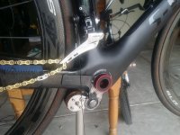
Bit the bullet and ground an 8mm hole in the seat post to run the wiring. Managed to hide all the wiring inside the frame with only a very small section of cable exposed at each end.


View attachment 3
Finally the bike was ready to roll and have its first shakedown.

So the first ride showed a few problems. Firstly the swing arm had too much flex in it and was distorting under load and not placing enough pressure on the tire.
This was rectified by adding a doubler plate to the swing arm. This got rid of all the flex in the swing arm with the drive to tire now being very positive.


View attachment 3
Finally the bike was ready to roll and have its first shakedown.
So the first ride showed a few problems. Firstly the swing arm had too much flex in it and was distorting under load and not placing enough pressure on the tire.
This was rectified by adding a doubler plate to the swing arm. This got rid of all the flex in the swing arm with the drive to tire now being very positive.
Similar threads
- Replies
- 29
- Views
- 1,476
- Replies
- 14
- Views
- 748
- Replies
- 50
- Views
- 5,574