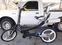
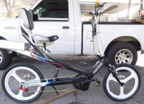
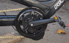
Giant Revive BBS02 Mid-Drive

LewTwo

1 MW
Joined
Apr 8, 2014
Messages
2,100
Location
Houston, Texas
Excaliburke said:
Wow, this is impressive! I had no idea it leaned *forward*.
'Lean forward' relative to the previous angle.

Excaliburke said:
Out of curiosity, is it possible to use the shock to compensate for a 395mm fork in some way?
Short answer is "No" but it depends on what one means by "compensate".

For example:
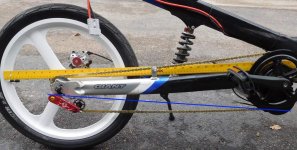
I figure installing the 395 mm air fork will increase the steerer tube angle from 30 to a bit under 34 degrees and increase the height of the crown above the ground by about 4 inches. In theory one could use a longer shock to increase the height of the back end an equal amount. However it would not restore the original steerer tube angle of 30 degrees (or the length of the trail).

P.S.
You might want to have a look at my previous thread.
Toward the end there is a discussion of the effects on the bicycle handling with the 395 mm air fork.
https://endless-sphere.com/forums/viewtopic.php?f=3&t=117000&start=25
 
Joined
Oct 17, 2020
Messages
16
LewTwo said:
Excaliburke said:
Wow, this is impressive! I had no idea it leaned *forward*.
'Lean forward' relative to the previous angle.

Excaliburke said:
Out of curiosity, is it possible to use the shock to compensate for a 395mm fork in some way?
Short answer is "No" but it depends on what one means by "compensate".

For example:
I figure installing the 395 mm air fork will increase the steerer tube angle from 30 to a bit under 34 degrees and increase the height of the crown above the ground by about 4 inches. In theory one could use a longer shock to increase the height of the back end an equal amount. However it would not restore the original steerer tube angle of 30 degrees (or the length of the trail).

P.S.
You might want to have a look at my previous thread.
Toward the end there is a discussion of the effects on the bicycle handling with the 395 mm air fork.
https://endless-sphere.com/forums/viewtopic.php?f=3&t=117000&start=25

Fascinating, bike geometry is kind of like black magic sometimes, isn't it. I was mainly looking at the angle of the seat, I think. (As it seems you are in terms of the 'lean') as sometimes it felt like falling forward a little bit. I feel like a little bit of front suspension with a cheap spring fork would be better than nothing, I'm just trying to find a way to do it without destroying the overall lean-y-ness.
 

LewTwo

1 MW
Joined
Apr 8, 2014
Messages
2,100
Location
Houston, Texas
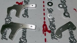
I received the pieces parts from "SendCutSend.com" last Tuesday. Excellent work and very fast delivery (thanks for the hint PapaSteve).
SendCutSend 00(2048).jpg
You may note that I got two of the 1/4 inch thick steel brackets. I had to thread 5 each M6x1 holes in that piece and I figured that there was every possibility that I might break a harden tap off in a hole and NOT be able to get it out. As it turned out I did break one tap but I was able to extract it.

There were several days on monsoons that kept me from working on the bike. When I finally did get to it then the local mosquito squadrons attacked in force. They seem to ignore the liberally applied DEET repellent.

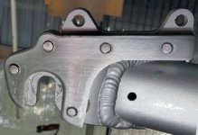
I first finished drilled the two holes in the SST bracket with a 5.0 mm ground drill. These were then tapped from the front by hand to M6x1 ... 1/4 to 1/2 turn clockwise, 1 turn counter-clockwise ... rinse (lubricate) and repeat. Then I ran the tap all the way trough from the back. Next I assembled the "Sandwich" using the 1/4 inch thick SST piece, 1/4 inch thick aluminum center and the 1/16 thick SST cover using M6 by 18 mm black-oxide steel cap screws to avoid and chance of galling SST fasteners. The sandwich was then mounted into the dropout using a M10 bolt, fender washer, 19 mm fit-up washer and nut. It was carefully aligned with the existing drop out and lightly tapped to insure that the aluminum center piece rested against the dropout. The M10 fastener was tightened and the fit-up rechecked. Then I ran a 1/8 drill through the center of the two M5 fender mount holes to mark the 1/4 inch thick SST bracket with their location. Everything was disassembled.

I first drilled holes in the SST bracket using a 1/8 diameter bit in a small drill press and with lots of lube. Then I used a 3/16 drill bit and finished off the hole with a 5.0 mm ground drill bit. That last bit was used more like a reamer. Each hole was drilled with all three bits before repositioning the work piece. Those two holes were then tapped as described above. The sandwich was assembled again. The fender holes in the dropout were drilled out with a 1/4 inch drill. The assembly was remounted to the dropout with the M10 bolt and an additional two black-oxide steel cap screws through the former fender holes. The position of the last hole was marked and center punched. A 1/8 bit was used to drill through the aluminum dropout and mark the SST bracket. Everything was disassembled.

The final hole was drilled and tapped as describe above. The sandwich was then assembled again. The assembly was remounted to the dropout with the M10 bolt and three black-oxide steel cap screws. The M10 bolt and nut were removed and the axle assembly was fitted between the dropouts to be certain that there was no interference. Five M6 x 16mm long SST button head cap screws were individually ground to length. The black oxide bolts were removed and replaced with the SST bolts one at a time. Loctite 243 was applied to each screw before assembly to prevent galling as well as secure the screws against vibration loosening. Then the axle assembly was removed.

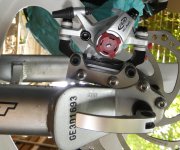
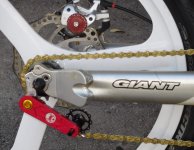
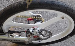
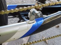
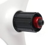
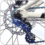
The 20 mm IS adapter was fitted to the disk caliper adapter with black oxide M6 x 18 mm long hex socket head cap screws. These longer bolts are needed to reach all the way through the adapter and the IS mount. I do not have any M6 SST screws of the proper length. The axle assembly was re-installed in the rear wheel along with the single speed adapter, a 16 tooth cog and a 160 mm disk rotor. The wheel assembly was installed in the rear dropouts using a 5 mm diameter QD skewer. Next the Avid BB7 caliper was mounted and the bolts left somewhat loose. The brake lever on the caliper was actuated and the bolts mounting bolts tightened. When the wheel was spun I noticed that the inside disk pad was rubbing against the rotor all the way round. The caliper was removed and two spacer washers were placed between the IS mount and the caliper. Then the caliper was tightened into position again. This time when the wheel was spun there was no rubbing sound. When the caliper is actuated it holds the wheel firmly. When it is released the wheel can be spun freely.

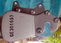
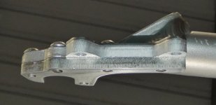
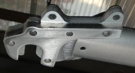
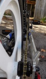
The following picture were taken with the bike upside down. The pictures have been rotated 180 degrees to show them in a more normal position.
Revice Rear Caliper Adapter X00.jpg
Revice Rear Caliper Adapter X01.jpg
Revice Rear Caliper Adapter X02.jpg
Revice Rear Caliper Adapter X05.jpg
Revive Rear Caliper.jpg

I should have ground another thread off that rear most cap screw but I am going to leave well enough alone. That leaves me with the problem of figuring out how to mount the Bafang speed sensor and magnet with 2-1/2 inches of space between the frame and the wheel spokes. Other real world events have been requiring my attention for the past several days.
 

LewTwo

1 MW
Joined
Apr 8, 2014
Messages
2,100
Location
Houston, Texas
Well I have gotten speed sensor mounted. First I had to determine if it could be mounted back-asswards ... and it can.
See my post on the Bafang speed sensor here: https://endless-sphere.com/forums/viewtopic.php?f=2&t=117707

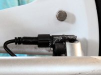
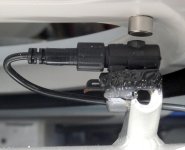
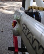
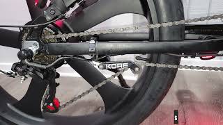
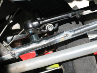
Next was to figure where to put it. The problem is that it is intended to be used with ordinary wire spoked wheels. My bike now has solid cast wheels and the closest those flat spokes come to the swing frame is about 2-1/4 inches. I wound up attaching the speed sensor bracket to one of the old cantilever brake mounts (the one on the non-drive side). I first used double sided tape and tie-wrap. That did not fell solid enough. So added a bit of wooden popsicle stick embedded in a layer of epoxy (JB WELD). Lastly I drilled a 10 mm hole in the spoke opposite of the inner tube valve. That hole lines up with the sensor ... well it comes very close to lining up with it. The spoke magnet was epoxied into that hole. I will likely cut the other cantilever mount off the swing frame so I have plenty of room to remove the wheel assembly. Also the cantilever mount on the drive side is too close to the chain path for comfort.

Giant Revive Speed Sensor 01(1024).jpg
Giant Revive Speed Sensor 02(1024).jpg
 

LewTwo

1 MW
Joined
Apr 8, 2014
Messages
2,100
Location
Houston, Texas
Long delay for this project because the battery I was planning to use was Tango-Uniform. I prefer LiFePO4 (aka LFP or Lithium Iron Phosphate) cells despite their lower energy density. My reasons are longer battery life, less prone to failure (safer), better tolerance to abuse and flatter discharge curve. I originally ordered 20 Ah Prismatic batteries but have no confidence in the cells that I received and frankly the pack would have been very heavy.

Time to cut my losses and start over with high quality Headway cells. I use a rule of thumb “throttle only, 1 mile per Ah at 48 volts”. I typically do not really need more than a ten mile range so I decided to make a 16S1P pack with Headway 10 Ah 38120S cells (that “S” appended to the end of the number means M6-1 screw terminals vs flat top which are also offered). The cells were ordered from EV Components.

These cells did NOT come with the button head M6-1 x 8mm long screws typically seen on headway cells. I should be getting those from Amazon today. Note that the negative terminals have a depth limit of 6 mm for threaded fasteners. Typical M6 flat washers are 0.5mm thick but 1.5 thick flat washers are available. Along with the terminal connector or buss bar that should be adequate for the 8mm long fasteners.

I am using the standard headway two hole plastic holders but the provided bus bars were steel. So I will fabricate replacement copper bus bars from 12mm x 2mm copper bar. I just happen to have a Daly LiFePO4 16S 30 Amp BMS among the “stuff” I have collected. I also happen to have some 30 Amp 58 Volt “Auto Link” fuses with M6 holes. I will put one of those on the positive terminal of the battery pack.

I am also getting a DC-DC converter to provide a 12 Volt 5 Amp power source for a power contactor, lights and other accessories as needed. Five amps is probably overkill. I also need to work out the parameters for the pre-charge resistor and coil drain diode. I am thinking “IN4004” for the coil drain diode. I have no idea for the pre-charge resistor (HELP).

Edit 23 Oct 2022:
I am a bit short on the copper bar I was going to use for the bus bars, so I broke down and just ordered copper bus bars ....
https://www.ebay.com/itm/294851322309
Copper is 10X more conductive than carbon steel.
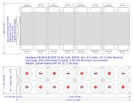
LFP-38120S-layout 01.jpg

Reference:
Battery Pack, 48 Volt 20 Ah LiFePO4 cells
https://endless-sphere.com/forums/viewtopic.php?f=6&t=117764

EV Components
https://endless-sphere.com/forums/viewtopic.php?f=3&t=117997

Amazon, M6-1 x 8 mm button head screws
https://www.amazon.com/dp/B07VPVBNV1

Amazon, M6 x 1.5 mm thick flat washers
https://www.amazon.com/dp/B07X14TGFX

Amazon, XWST DC-DC Converter
https://www.amazon.com/dp/B0B5KRJSKK/
 

Attachments

  • Headway 16S1P 38120 Battery Pack.zip
    74.6 KB · Views: 3

amberwolf

Administrator
Staff member
Joined
Aug 17, 2009
Messages
39,115
Location
Phoenix, AZ, USA, Earth, Sol, Local Bubble, Orion
LewTwo said:
I am also getting a DC-DC converter to provide a 12 Volt 5 Amp power source for a power contactor, lights and other accessories as needed. Five amps is probably overkill. I also need to work out the parameters for the pre-charge resistor and coil drain diode. I am thinking “IN4004” for the coil drain diode. I have no idea for the pre-charge resistor (HELP).
I think I have some math on that in recent post (I may be thinking of something else); I'll see if I can find it and link it here.
 
Top