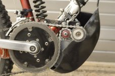
GNG, 1000W 48V BB-drive, $400

I believe you might be able to spin one up on the bench unloaded with an RC ESC, but...even unloaded it might damage the ESC. I am certain that if you tried to run one on a bike, the ESC would fry very rapidly.
 
Any idea how to disassemble GNG v1.1 jackshaft. It is metal tube and inside are sealed bearings and shaft. Is it press-fit? How I disassemble it?
At right side bearing seal is worn/broken probaly because bearing does not move and shaft turns inside bearing! For some reason shaft is not tightly inside bearing.

Probably I need to replace that bearing.
 
I just took my LR jackshaft apart. If it's similar, you'll need to use a gear puller to remove the sprocket and the pulley. Hold the body of the jack shaft and smash one end of the axle on a block of wood. It should push the other side bearing out with the axle. Use the axle again to push out the remaining bearing.
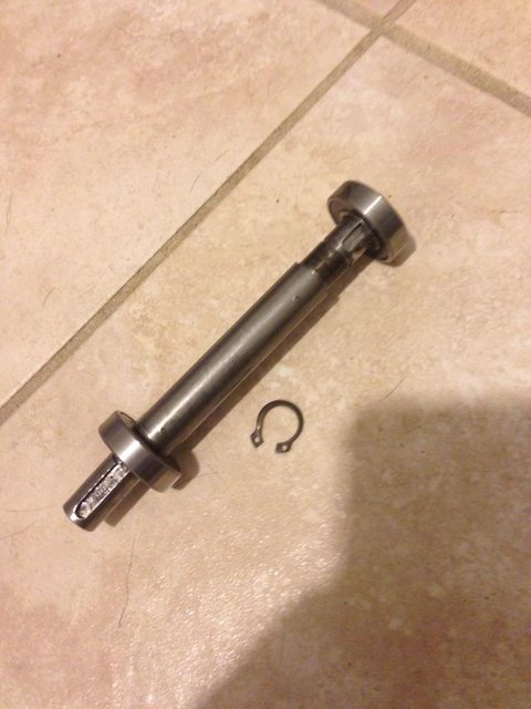
It's literally just this inside the body (axle, 2 bearings and a snap ring)
W4VNd0dl.jpg
 
Thanks. Right now I i already pushed bearing back inside (put flat screwdriver on the edge of bearing and tapped gently with hammer) and now it is tight on axle and bearing started to turn again together with shaft. Seal is still broken but I have it filled with grease and I put big washer to cover bearing.
Maybe later I follow your advice to disassemble it, right now it works as it is.
where is that snap ring located?
 
So I had a thought regarding the stock GNG kit regarding top speed for those people who may use this kit with a commuter rather than for off-road-only use: What about the idea of modding the internal shunt to allow 30 amps, then swapping the position of the chainrings on the bottom bracket?

The extra amps should keep the torque at nice levels, while the swap in chainrings should allow for a higher top speed (assuming the final gear on your rear wheel is 11-tooth or something similar).

Granted, this would make pedaling at top speed totally impossible, but that's already the case with the stock setup at top speed anyway.

It seems like a really cheap (read already paid-for) way of getting some more speed out of this system if you're gonna be riding mostly streets/paths. I'd love to hear feedback on that idea.
 
Disregard my last post about swapping chainrings. It was late and I was having a brain fart. I ran the proper calculations to determine the best gearing/speed for my needs.

I do have a question about the stock jackshaft on the GNG1.1 kit though. I pulled my motor apart to rewire it and in the process I noticed the the jackshaft is awfully stiff. I can spin it with one finger in the belt pully, but it doesn't spin freely. It seems to me the this would be a big power drain if the jackshaft is causing drag.

Have any of you also noticed that the jackshaft is really stiff and if so did you do anything to make it spin more freely?
 
Are you sure you aren't shorting the phase wires?

That happened to me while rewiring and the jackshaft was really hard to spin.... I needed a ggod half hour before noticing that the connectors on the controller side were touching...
Once separated the phases the jackshaft was smooth as butter.
 
k1kk0_1t4 said:
Are you sure you aren't shorting the phase wires?

That happened to me while rewiring and the jackshaft was really hard to spin.... I needed a ggod half hour before noticing that the connectors on the controller side were touching...
Once separated the phases the jackshaft was smooth as butter.

Thanks for replying, sorry for not being clearer. I was talking about the jackshaft with everything pulled apart. The shaft isn't connected to anything at the moment. Its just in the upper plates with the pulley and sprocket still attached. I'm pretty sure it's just the bearings, but I'll need to get the pulley and sprocket off so I can get them out and inspect them.

I was just wondering if other people with the kit had noticed that the jackshaft is stiff, or rather doesn't really free-spin at all. I figured it should spin more like a bottom bracket does. Mine is much more stiff than that.
 
That's strange: i have two gng kits (the new model chain driven) and I haven't noticed that problem... But we know that the gng isn't an example of excellent manufacturing.

Probably as you said bad bearings or a bent axle (maybe damaged during shipping).

The freewheel should be threaded on and not too difficult to extract from the jackshaft.
(Somewhere in this thread there is someone explaining how to disassemble the jackshaft but in practice you need something to gasp the notches on the back of the freewheel and an old chain (or that tool you use to disassemble old style freewheeling cassette, sorry don't know the name in English).
 
You most likely have a bearing spacing issue as mine did originally or the bearings are not fully seated in the pockets due to some machining debris. Simple way to check is there should be a slight amount of axial play in the shaft assembly when fully assembled. Use a plastic mallet and lightly tap on the shaft end, one side and then the opposite side. You will want to do this with most dual bearing setups to seat the outer bearing races into the housing. Shaft and bearings should move a few thousandths. If not, just pop out the bearings and make sure there is not some crud behind them keeping the outer races from fully seating and causing the balls to side load between the inner and outer races on each bearing cassette.
 
Awesome info guys, thank you! I'm waiting for a set of pullers to arrive from harbor freight and as soon as I have them I'll get the pulley and freewheel sprocket off to check the bearings.

I've read all the stories of lousy assembly on the GNG kits and I've seen it firsthand.

I just rewired my GNG motor and during disassembly discovered that the bearings on the shaft were not seated well with the side cases. Again when my pullers arrive I'll be properly seating the bearings in the side plates before I put everything back together.

Side note: if you guys are interested, I'd be happy to post pics of the rewire. I replaced the stock wires for the phase and halls with high-temp turnigy silicone wires. I also used an XT-60 three wire connector for the phases and a nice little 5-pin servo-style connector for the halls. It's much nicer than the crap they use stock.
 
So here's the pics of my rewire on the GNG motor.

I started with the hall wires. Here you can see the originals soldered to the PCB where the hall sensors are connected and the replacement 26AWG high-temp silicone wires I'll be using to replace them.
gng_motor_rewire-1.jpg


Here are the new wires soldered onto the PCB. I used a piece I had found on HobbyKing that had the 5-pin (JS2 I think its called) servo-style connector already wired up. It was the only male 5-pin I could find on the site, and I ordered it because I was getting the wires at the time and it was cheap. I ended up having to swap blue for white but since the other connector that plugs in here has the same colors it won't be a big deal to keep track of. The rest remained the same colors.
gng_motor_rewire-2.jpg


Next I moved to the phase wires. I trimmed back the originals as close as I could to the windings while still leaving enough to work with. For the phases, I used 14AWG high-temp silicone wires. This was the first time I tried to splice this high-strand wire onto more traditional stranded wire, and I had a bit of trouble keeping the wrap tight as I soldered, but it is still a strong connection, so I think it'll be fine.
gng_motor_rewire-3.jpg


Here's a pic of the 3-pin XT-60 connector I found on HobbyKing. It's designed for use with 14AWG, so the fit was perfect for this application. the connector is keyed, so there's no risk of connecting it in the wrong orientation. I labeled the corners as I was working on this so that there wouldn't be the chance of me soldering stuff on the other end in the wrong order. After the other side of the connector was soldered up, I cleaned off the ink.
gng_motor_rewire-4.jpg


This is a shot of the completed wiring before I tucked the wires into the opening in the case. You can see how much cleaner these connectors are compared to the stock stuff.
gng_motor_rewire-5.jpg


Since there was no way I'd ever be able to use the original rubber block that went around the stock wires with the new thicker wires I installed, I ran a bead of silicone around the case opening and seated the wires in it. I then squeezed a little more into and around the wires, and shaped it a bit with a toothpick. I left a little ridge at the side case face to help seal that area when i button the motor back up.
gng_motor_rewire-6.jpg


And here's a final shot of the completed rewire. I was really happy with how everything came together. It's the first time I replaced the phase and hall wires on a motor.
gng_motor_rewire-7.jpg
 
zro-1

great pix!

i was just wondering what your thoughts are on the waterproof-ness of the motor as it comes from the factory, since you've opened it and all. you think that rubber block where the wires go into provides a good seal. i've hosed off the motor with water perhaps a half dozen times so i'm wondering if i may have gotten water inside...
 
Overclocker said:
I was just wondering what your thoughts are on the waterproof-ness of the motor as it comes from the factory, since you've opened it and all. you think that rubber block where the wires go into provides a good seal. i've hosed off the motor with water perhaps a half dozen times so i'm wondering if i may have gotten water inside...

I'd say the rubber block is fine for hosing off with a garden hose. I wouldn't use a pressure washer though. More importantly, the side plates on my motor weren't sealed. Some of the motors were coming with the side plates sealed with a bead of high-temp silicone around the seam. The side plate fitting in general is pretty tight and does have a lip, so it would probably be fine with rain, splashes, and a garden hose, but anything more could introduce water to the internals I'd imagine.

The big unknown here is that the quality tends to vary quite a bit, depending on what generation kit you get, and who happened to assemble it. I doubt that GNG has much if any quality control. I'd say at most they verify the thing spins when power is applied then ship it out.
 
Hi,
i would like to get some dimensions/specs:

1) jackshaft nut that holds freewheel - It has become loose and I lost it while riding. I know that I used 12mm socket wrench when servicing freewheel. Tried other standard metric nuts and closest was 13mm outer, 6mm inner, but thread pitch was different so it is used temporarily and just holds about one turn.

2) jackshaft bearing dimensions - I would like to buy new ones before taking it apart. I have bearing with broken seal - i can see balls, temporarily covered with big washer and lots of grease.
 
Earlier, I posted a pic of my #25 chain with a dreaded serpentine wrap and a nylon(?) fixed idler. packed with teflon grease and fully enclosed, it is super quiet. I thought what is good for the primary is good for the secondary.
_DSC3074.JPG
With more teeth engaged, it is quiet, snappy and runs more smoothly. I lube with teflon liquid nearly every ride.
pics with the season's mods:
https://www.flickr.com/photos/55376116@N02/albums/72157659479930988
 
11mm ID shaft >> (M30 x 1) 13T - 14T - 15T Freewheel adapter <$17
For 11mm shaft w/4mm key

Now, Alloy version available!

Compatible with
MY1018z - 250-450w motor
XYD-16 - 250-450w motor
MY1016z3 - 350w motor
GNG BB Drive (11mm shaft w/4mm key)

- $16.95

Steel version available ... check below description.
 
Back
Top