Gradual, smooth, progressive throttle? HOW??

briogio

100 W
Joined
Dec 28, 2010
Messages
240
Location
Cookstown, Ontario, Canada.
I built my first Ebike with a BMC V2T as a mountain bike, after a ride I realized it wasn't going to work, I couldn't modulate the throttle and stop it spinning up (front wheel drive) :shock: . So I put slicks on it and now I'm having BIG fun on the street :lol: .

Now I want to build my next Ebike with a Surly Pugsley (rear wheel drive) and I'm wondering how I can get a gradual, smooth, progressive throttle, is it in the throttle unit?, the controller?, the motor?, I know I'm really going to need one for snow and general mountain biking.

Thanks for the education that this site has given me for over 2 years now! :wink:
 
I have heard that the 12-FET controller has a smoother response compared to the popular 6-FET and 9-FET...I don't know why, perhaps it had something to do with the programming.

Matt (recumpence) sold several builders a Magura throttle that has an added voltage regulator, so the voltage signal is smooth, AJ mentioned that his gave his motor a smoother response even at low RPMs. Best of luck...
 
briogio said:
I built my first Ebike with a BMC V2T as a mountain bike, after a ride I realized it wasn't going to work, I couldn't modulate the throttle and stop it spinning up (front wheel drive)
Hmm... That's new to me. I have built 5 ebikes and have not encountered this problem. I have never use a BMC hub though. Is this a hub problem, a controller problem or a throttle problem. I would like to know so I can avoid it.
 
Methods is working on somthing.

Right now with a fresh charge @ 125v... my bike will flip me off if I'm not careful. I can't wait for his throttle adapter to be ready!
 
SamTexas said:
I think I understand now. You guys are talking about crazily high power systems, 2kW and above, right?
10 Kw and above :D
I got used to it, and in town i can switch to lower speed with the 3 speed switch if i want to cruise.
In the mountain I like the trial like, brutal torque that my V 10 has.
The beast wants to climb on top of anything ahead of it, took me some time and bruises to get used to.
I don't think a BMC can come close to the 5404 pulling 15 KW off my Lipo, else it would tear its gears and clutch on the first start.
The trick is your posture need to be as aggressive as the bike is. Ride for torque and torque you will like.

Then, better throttle modulation should come available soon, simply because so many of us would like it.
 
How do you guys use your pedals? As footrests?

We always use the pedals...whenever we see the police. Otherwise, you need to give the pedals a rest whenever possible, to prevent excessive wear and heat on the bearings. My BB-bearings are fresh as new!
 
spinningmagnets said:
We always use the pedals...whenever we see the police. Otherwise, you need to give the pedals a rest whenever possible, to prevent excessive wear and heat on the bearings. My BB-bearings are fresh as new!
Ok, sounds excessively reasonable to me. Case closed.
 
Regarding the throttle response, some throttles are made differently from others. It is probably in the positioning, type, and strength of the magnets inside, as the sensors are probably all the same copy of a Honeywell "analog output" (ratiometric) hall sensor.

For instance, the throttle sent with the Fusin review kit was VERY touchy with quite a large dead spot at the beginning, and then suddenly starting up at something a fair bit beyond "barely moving" the motor.

But an older throttle I already had laying around has a very smooth transition from off to on, and not much (if any) dead zone. Unfortunately I have no idea what company made it or sold it, but I have an identical one on CrazyBIke2.


So, you can probably take your existing throttle, and play around with the positioning of the magnets inside it to change the deadzones. If you change the strength of the magnets, it will change teh way the fields overlap and how the sensor responds to them. If you change the type of magnets, it changes how the field strength changes from surface of magnet to "outer edges" of the field, which can change the "curve" of throttle response in different ways.
 
Let me guess - you have an EB2 controller instead of an EB3.

On my MAC motor, the throttle was more like an on/off switch than anything else with an EB2. It would also jitter ( like rapidly turn on and off ) at anything other than 100% throttle. The higher the voltage, the higher the speed, the worse the problem was.

It was buttery smooth when i got my newer cell_man EB3. The difference was huge. I was about to give up on geared motors altogether until i got that controller!

The problem is the controller, not the throttle signals it's interpreting. Don't waste your $ on switching throttles or trying to do throttle smoothing stuff - if you hooked up a DD motor to the same controller, it would modulate the power just fine.

Where'd you get your controller from?
 
neptronix said:
Let me guess - you have an EB2 controller instead of an EB3.

On my MAC motor, the throttle was more like an on/off switch than anything else with an EB2. It would also jitter ( like rapidly turn on and off ) at anything other than 100% throttle. The higher the voltage, the higher the speed, the worse the problem was.

It was buttery smooth when i got my newer cell_man EB3. The difference was huge. I was about to give up on geared motors altogether until i got that controller!

The problem is the controller, not the throttle signals it's interpreting. Don't waste your $ on switching throttles or trying to do throttle smoothing stuff -

When did EB3 boards come out? How can I tell if mine is EB3? Got mine from Cellman.

What about EB2 @ 25A & 48v? Still an issue w/throttle??? :?:

What about Flash USB upgrade for older EB2 or change settings somehow???
 
The cell_man eb3 came out mid-late 2011.

I tried every possible thing on the EB2 to make it smooth, including switching throttles, trying out every parameter, and modifying the board. The fact is that the controller can't handle that high electrical RPM of a MAC/BMC motor well at all.

Open your controller up and look at the circuit board.. it'll say EB212 or EB312 if it is a 12FET.

Lyen EB3's ( aka mark 2 controllers ) should work fairly well, but cell_man's EB3 has some customizations that supposedly make the MAC/BMC motors perform better with it.

deVries said:
neptronix said:
Let me guess - you have an EB2 controller instead of an EB3.

On my MAC motor, the throttle was more like an on/off switch than anything else with an EB2. It would also jitter ( like rapidly turn on and off ) at anything other than 100% throttle. The higher the voltage, the higher the speed, the worse the problem was.

It was buttery smooth when i got my newer cell_man EB3. The difference was huge. I was about to give up on geared motors altogether until i got that controller!

The problem is the controller, not the throttle signals it's interpreting. Don't waste your $ on switching throttles or trying to do throttle smoothing stuff -

When did EB3 boards come out? How can I tell if mine is EB3? Got mine from Cellman.

What about EB2 @ 25A & 48v? Still an issue w/throttle??? :?:

What about Flash USB upgrade for older EB2 or change settings somehow???
 
Hey guys,

I've just got my MAC 12T running on 40a and its a bit fruity, I have wheelied off the back twice today and need a little more throttle modulation....and maybe some more skill as well. Did anyone find a solution to this issue? The standard Mac throttle I have is pretty much on / off. Supplier for the magura anyone?

Big thanks!
 
Your best investment for your setup is probably a Cycle Analyst V3 (still in beta).This will give you:

  1. Current or Power Throttle - a feedback-based throttle that maps the % of WOT into % of MaxAmps or MaxWatts. This fly-by-wire system goes a long way towards getting the non-linearities of your combined throttle/controller/motor trio under control. The Power Throttle (vs Current Throttle) holds up performance with battery sag, end-of-discharge voltage roll-off, and cold weather running.
  2. The ability to hook up LMH (Low,Medium,High) power switch to scale the % of MaxAmps or MaxWatts before the thrilled scaling is applied. For instance, you might set up LMH settings of 500W, 1000W, 2000W so your throttle is much more refined for slower situations.
  3. Throttle ramping - this is the biggie for flogged gear motors - it lets you configure the how fast the throttle is applied so your gears and clutch don't vaporize in spite of over-enthusiasm at the helm.
There are more advanced adaptive algorithms coming that you can flash into the firmware, but realistically, that won't be for a while.

If you can't wait, your controller may accept an LMH switch and a CA v2 will give you Current Throttle (see section 9.3 of v2.23 manual).

I run BMC gear motors with a CA V3 and can piddle along on bike paths with a max of 490W available and super refined throttle control, or WOT 3300W off the line to smoke cars across intersections - no wheel spin and happy gears. :D
 
Wow, this sounds ace Tek. I have already have a three speed switch, but the progressive power roll on advanced modulation stuff sounds like the business. Would be interested to learn a bit more about this, will certainly pay the grin cyclery a visit though.
 
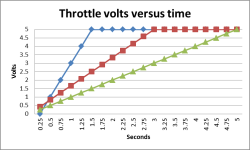
Don't controllers use a signal for throttle ranging from 0 to 5 volts? Sometimes they get it from a throttle, or a pedelec sensor, or both.

I guess it'd be easy to make a small arduino controller for 20 bucks to ramp the throttle based on the input. The delay to slope the ramp-up function could be dialed in. There's probably a simple analog electronics solution using a capacitor to soak up an initial shock, maybe someone else versed in Analog might be clued in.

Any idea if ramping the 5v signal would work? Or am I 'barking up the wrong end of a red herring?'

New Picture.png
 
Samd said:
Don't controllers use a signal for throttle ranging from 0 to 5 volts?
It's usually more like a 0.8V (or more) to 3.8-4.5V. You'd have to measure your actual throttle output voltage while testing motor RPM to see what the actual usable range is on your controller. Push up the throttle voltage until the controller starts spinning the motor (no load), back off till it turns off then note the middle of those voltages down; that's your zero-crossing of throttle. Then throttle all the way up slowly watching RPM, wehn the RPM no longer climbs that's your max throttle input voltage; turn throttle down a bit till RPM begins to drop (allowing for freewheeling, or maybe put a very very slight load on it so it will slow immmediately upon throttle reduction), then back up till RPM increases, then note the middle of the two voltages and that's your peak throttle voltage input.
 
Interesting. I wonder if some of us aren't hitting peak power output from the controller as the controller doesn't receive the full 5 volts...
 
The controller doesn't *use* the full 5V, is my point. At least, with most of them. That voltage range I give is not just the throttle output range, it is also the input range for the controller--yours may ahve a label on it to tell you what it sees.

For instance, on my Fusin controller from the review kit:
http://www.endless-sphere.com/forums/viewtopic.php?p=583257#p583257
it says "1.2V-4.4V" for the throttle input range. That means that is all it will respond to, so you get zero RPM for anything up to 1.2V, then max RPM at 4.4V; anything higher does not increase it's output--it's at max.
file.php


I've seen other voltage ranges on various controller labels, too.
 
Samd said:
I guess it'd be easy to make a small arduino controller for 20 bucks to ramp the throttle based on the input. The delay to slope the ramp-up function could be dialed in. There's probably a simple analog electronics solution using a capacitor to soak up an initial shock, maybe someone else versed in Analog might be clued in.

Any idea if ramping the 5v signal would work? Or am I 'barking up the wrong end of a red herring?'

Nope - pretty fair barking, actually. :D If you search ES you can find discussions of all these ideas - ranging from adding trimpots/resistors to each end of a Magura so the true range of motion matches the controller input to using magnets or special uproc controllers to alter the throttle curve.

Best to use Google to help you search using a Google search string of 'site:endless-sphere.com <search string>'
For instance: 'site:endless-sphere.com throttle curve'

Here's some related references:
How to change my throttle output signal
anyone used the 'current throttle' option for CA's?
changing curve via RC
Beta CA build for R/C controllers
 
Back
Top