May be worth checking... verify that you have good continuity between the hall sensor terminals and where the new wiring will go on the pristine solder points. (Nothing scuffed up or damaged in the traces.)
Have all the sensors fronts (with the part stamp) facing the magnets.
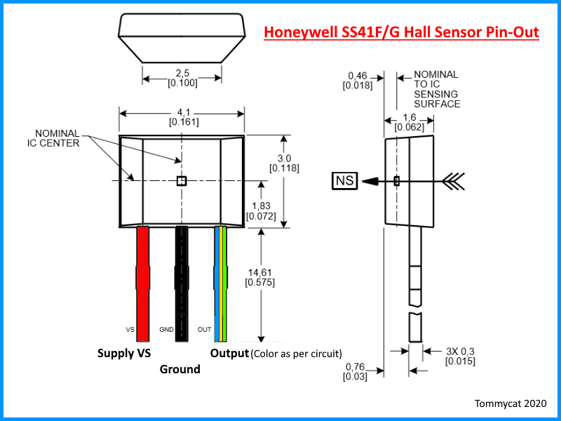
All the 5V legs have continuity to the +5V. All the ground legs have continuity to the Ground symbol pad.
And the respective signal legs go to their designated pads of a, b, and c. Use this for reference...
The last wire (WHITE)currently attached to the 'S' pad is for a speed input.
So 6 wires total if your using the speed wire.
You're adding new wires of course, and the voltage readings from the controller's signal output sounds correct. So, no worries here.
Your controller appears to accept both normal angles, so I think not an issue.
Now you could just add 3 new wires as the same size and type as the current 3.
But a more elegant way would be to perhaps buy a cable with 6 conductors with the wire colors of
RED, BLACK, WHITE, BLUE, YELOW, and GREEN. The current draw is minimal... (< 20 mA) I.E. wire size can be minimal, but not to the point of easy breakage.
The open area in which to get the wires through may be an issue. Drop the speed sensor if you're not going to use it and go down to 5 conductor cable if needed.
The difficult part in my mind would be the tucking in and securing of the hall sensors between the stators.
Just a thought would see if I could get them all snugged and glued in, THEN place the board on top for final hall sensor solder terminations.
But whatever works best!
Great video to give you an idea of locations. ( I just glanced at it, so sorry if some of this was gone over already...
")
Best of luck!