markz
100 TW
ebay seller HKSUNWIN
48V 1500W
Wanting to change the LVC to 33V for 10S battery.
HKSUNWIN does not sell 36V controllers and I dont want to buy yet another controller.
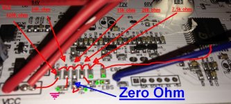
Locating LVC solder tabs, I needed a magnifying glass
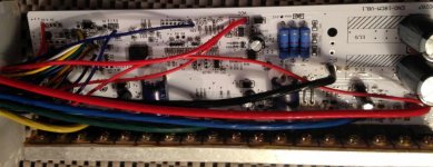
Caps 63V
FETS are EZ95N13 K733
84V - 72V - 60V are labelled and 48V LVC is when non of the pcb solder tabs are jumpered.
View attachment 4
Posting this before I accidentally lose it.
OK Back again
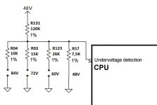
84V = 10K ohms
72V = 15K ohms
60V = 26K ohms
Cant find no 48V pcb tabs that are labelled, I am assuming if no tabs are jumpered then its 48V, as mentioned earlier.
Once lvc tabs are shorted, it goes straight to ground.
Havent been able to follow VCC, so must be another input once connectors (Anti-Theft 4 pin connector, 3 are used and large blade single in harness are connected.
View attachment 3
View attachment 2
Extra Info
https://endless-sphere.com/forums/viewtopic.php?f=2&t=71128&hilit=lvc+resistors&start=225#p1194721
http://www.datasheet39.com/PDF/925066/GPM8F3116A-datasheet.html
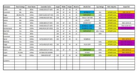
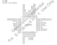
48V 1500W
Wanting to change the LVC to 33V for 10S battery.
HKSUNWIN does not sell 36V controllers and I dont want to buy yet another controller.
Locating LVC solder tabs, I needed a magnifying glass

Caps 63V
FETS are EZ95N13 K733
84V - 72V - 60V are labelled and 48V LVC is when non of the pcb solder tabs are jumpered.
View attachment 4
Changing to a LOWER LVC
methods - https://endless-sphere.com/forums/viewtopic.php?f=6&t=94790&p=1399473#p1388267
methods - https://endless-sphere.com/forums/viewtopic.php?f=6&t=94790&p=1399473#p1388267
To adjust lvc one needs to measure the actual cut out voltage
Then measure the resultant voltage divider voltage
Then swap 1 resistor such that the output of the divider is equal for a new input voltage
I = V/(R1 + Rbottom)
I * Rbottom = resultant trip voltage
As pack V drops so does trip V
A larger resistor Rbottom will raise LVC
Proof, at a fixed voltage the ratio of voltage between R1 and Rbottom swings, as they must divide 100%.
The math is very easy on paper
Harder in prose
Properly done in a spreadsheet with formula
Draw the divider
Enter your desired pack LVC voltage
Enter your fixed trip voltage
Calculate your Rbottom resistance
Vtrip = 1V (made up)
3V*12=36V
36V/Rt = I
1V/I = Rbottom
36V/Rt = 1V/Rbottom
36 = Rt/Rbottom
R1 was fixed therefore we now have Rbottom
https://endless-sphere.com/forums/viewtopic.php?f=2&t=94946&p=1390623&hilit=voltage+divider+lvc#p1390623
https://endless-sphere.com/forums/viewtopic.php?f=14&t=85824&p=1255840&hilit=voltage+divider+lvc#p1255840
Or you can hack many of them to change the LVC (finding the voltage divider that lets the MCU know what that is) or the current limit (altering the shunt or the sense circuitry between shunt and MCU).
https://endless-sphere.com/forums/viewtopic.php?f=14&t=85824&p=1255840&hilit=voltage+divider+lvc#p1255840
in a voltage divider somewhere on the battery-input side of things near the MCU chip, but each controller is designed differnetly so you'd have to trace things out and measure voltages to find this. Probably it will have one end of the divider at battery positive (probably from the keyswitch wire) and the other at ground.
Posting this before I accidentally lose it.
OK Back again
84V = 10K ohms
72V = 15K ohms
60V = 26K ohms
Cant find no 48V pcb tabs that are labelled, I am assuming if no tabs are jumpered then its 48V, as mentioned earlier.
Once lvc tabs are shorted, it goes straight to ground.
Havent been able to follow VCC, so must be another input once connectors (Anti-Theft 4 pin connector, 3 are used and large blade single in harness are connected.
View attachment 3
View attachment 2
Extra Info
https://endless-sphere.com/forums/viewtopic.php?f=2&t=71128&hilit=lvc+resistors&start=225#p1194721
http://www.datasheet39.com/PDF/925066/GPM8F3116A-datasheet.html


