Hall and Phase combo reverse myth busting?

DanGT86

100 kW
Joined
Sep 6, 2012
Messages
1,187
Location
Saint Louis MO
Hi all,

I set up a C80100 130kv motor today with an adjustable external hall board. I then tried all 36 hall/phase combos and found 6 that work. 3 CW and 3 CCW. All combos ran 5.5amps no load @ 5k rpm on 36v. That all makes sense to me and sounds reasonable as far as I know. I adjusted the hall board position until I had the lowest no load amp draw. The same timing position seemed to work in both directions as the lowest no load current.

I have read in countless places that reversing a brushless motor only requires switching any 2 phases of a running combo. This 2 phase swap is also stated in the first paragraph of the ES wiki on phase combos.
https://endless-sphere.com/w/index.php/Determining_the_Wiring_for_a_Brushless_Motor

Now for my question: How come I have NEVER been able to reverse a motor by swapping only 2 phases?

Upon examining my 6 running hall/phase combos from today's test on the 80100, there are NO reverse rotation combos where the direction change resulted from only 2 switched phases. In every single case the direction of rotation only switched when all 3 phases were switched.

So is it just me? Could it be the timing of my external hall board causing me to make the wrong determination about successful combos? Does the hall board need to be advanced specifically for each direction? Does this "swap any 2 phases" method only apply to sensorless operation? I have never found it to be true on any motor I have set up.

Thanks for any insight. I would really like to understand the theory rather than just finding a successful combo and moving on.
 
You need to swap the proper phase wires and the same colored halls wires.

Phases and halls must be ordered "A" then "B" then "C (A,B,C)
But they can also be ordered B,C,A OR C,A,B for a given rotation direction.
For the reverse rotation direction, you would order the phases and halls C,B,A OR B,A,C OR A,C,B

Make sense?
 
If you are using Hall sensors, the there are nine Hall sensor legs that have to be arranged. Each hall has a red/positive...plus a Black/negative...and they are bundled together into two wires that exit the axle (red and black).

The remaining three Hall legs are the 5V signal wires (resulting in five skinny wires exiting the hubmotor). The 5V signal is on/off back to the controller. Hook up the red / black wires to the proper positive/negative, and then don't touch them.

The three signal wires need to also be switched from forward to reverse. The center Hall will not change its position, but the other two have to trade places.
 
Switching two phase wires will reverse a motor used with a sensorless controller.
With hall sensors, the hall signals need to be also moved to reverse it.
 
Thanks for the replies. It makes sense that switching any two wires would reverse the order in a sensorless setup since it doesnt matter where in the sequence you start. Hence ABC with B and C switched becomes A-CBA-CBA. Correct sequence just different starting point. I always thought the sensored and sensorless control functioned the same way but sensored just provided more accurate timing. I guess that is why I am struggling to understand what is happening in this case.

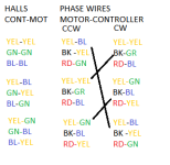
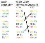
I guess the problem is that going over my data collected today I cant find any instance of rotation reversal where just 2 phases or halls were swapped. Pictured below are my successful combos. Black lines represent the combos that were the same at the motor but reversed rotation from changing the halls. The Phase connections really only had 3 unique combos.
So either
1.I am missing something obvious in my data
2.The external hall board is so far advanced or retarded that it is allowing bad combos to spin or preventing good combos from spinning.
3.I have 60deg or 120deg hall spacing set wrong in the controller
or
4.The swapping 2 phases to reverse is just not true when sensored.
5.I just don't get it.

HALL PHASE.png
 
DanGT86 said:
4.The swapping 2 phases to reverse is just not true when sensored.

This is the right answer. You need to swap a pair of phase wires and rotate the sequence of the hall signals to reverse.
 
Not that it's a given, but arent the phase and hall colors supposed to and usually corrolate? For instance, if you want to reverse a known-good setup where hall and phases are already color coordinating, swapping 2 phases and 2 halls of the same color sets should reverse the setup. I think Teslanv said the same above?

You need to swap the proper phase wires and the same colored halls wires.
 
That depends on how your motor and controller were wired, and which colors end up working in the first place. It could be completely random. (certainly feels like it :lol:)

Also, some controllers (and motors) may not even have different colored wires. I have one controller here with all green wires for phase and halls (probably because it has self-learn, and a reversing-function wire pair), and I've seen a pic of an unmodified hubmotor here on ES somewhere a long while back that had all one color wire, but I don't remember what kind it was.

Some of the motors I've opened up have the same color order for phases and for halls, and some don't. For example, I've had at least 3 9C 280x type hubmotors opened up here and all three had different color orders for hall and for phase, both relative to each other and within the motor itself. :/


However, if you look inside the motor, and find which color wire goes to which hall, and which phase, and they are all in the same order there (they aren't always), and then look inside the controller to find which color wire goes to which hall and which phase, and *they* are all in teh same order, then it's easy to find the right combos, including the reverses.
 
If sensored swap any 2 phases and find the right hall combo to match is one way.

Another way is to swap any 2 halls, and find the right phase combo to match.

Activating your controller's reverse switch is the last way. Other ways that people mention are simply advice coming from people who don't understand the simple math/logic puzzle of wiring controllers. It is never necessary to waste time trying all 36 possible wiring combos. Instead spend some of the time saved in gaining an understanding that since they're spinning in a circle that the firing sequence of A-B-C is the same as B-C-A and C-A-B. That means you swap any 2 for the same result of B-A-C (same as A-C-B and C-B-A)....helpful hint if the light bulb hasn't gone off, A-B-C is A-B-C-A-B-C-A-... no matter where you start.
 
There are two different systems for Hall Sensors, and so it may or may not be as simple as swapping the Hall sensor wires. It has been awhile since I researched that but in one case one of the hall signals is inverted, so swapping a pair won't necessarily compensate for a swapped pair of motor phase conductors.
 
Other ways that people mention are simply advice coming from people who don't understand the simple math/logic puzzle of wiring controllers. It is never necessary to waste time trying all 36 possible wiring combos. Instead spend some of the time saved in gaining an understanding that since they're spinning in a circle that the firing sequence of A-B-C is the same as B-C-A and C-A-B. That means you swap any 2 for the same result of B-A-C (same as A-C-B and C-B-A)....helpful hint if the light bulb hasn't gone off, A-B-C is A-B-C-A-B-C-A-... no matter where you start.

The light bulb has gone off with the ABC being the same as BCA and CAB. I get that it is just a different starting point. I tried all 36 combos because I wanted to pay careful attention to the current draw and behavior of each one. In the past I have noticed that some bad combos spin slowly and are loud and others just lock the motor. I figured comparing notes on failed combos would be educational as well.

So the part I am having so much trouble with is this:
Take a close look at my successful combos. There is no case in my results where only 2 phases traded places. In each case all 3 phases were matched with a new partner. That is where I am hung up. The swap any 2 rule didn't occur at all. Same goes for the halls. There was no case where switching just 2 halls produced reverse rotation. In every case all 3 halls got a new partner.
HALL PHASE.png
 
You can't chop off the 1st 2 sentences of my post, which both say swap 2 AND find the right combo of halls (or phases if you swapped 2 halls for reverse).

Incorrect wiring configs can often still spin a motor, but the resulting timing is so advanced or retarded that these false positive spinning results are dangerous to the motor and/or controller due to high resulting currents and heat combined with low torque.

Finding a good wiring config is a very simple matter, and where most people go wrong is swapping both halls and phases at the same time, and swapping 3 wires at once (which makes it harder to be systematic). Every phase combo has one good hall combo, and every hall combo has one valid phase combo. Of the resulting 6 valid, 3 are forward and 3 are reverse, so keep it simple by keeping either the halls or phases static (whichever is more difficult to swap) while finding the valid combo of the other set. If the good one is a reverse, swap 2 (any 2, only 2) of the set you kept static, and find the new valid combo of the others for forward rotation.

3 phase wiring is really quite simple, so I never worry about color coding or waste time looking one up. With a bit of workbench organizing I could easily do it blindfolded.
 
Wasnt trying to distort your message by chopping the quote.

I took the motor apart and re-terminated it in WYE today. I'm going to set everything back up and work on my hall board timing. There was 1 combo I found before that gave seemingly good rotation in both directions depending on where the hall sensor board was positioned. I'm really thinking the hall sensor "timing" is too big of an unknown for me to make any positive determinations about successful vs unsuccessful wiring combos. The current WYE termination is the way the motor will actually be used on the bike so now I will be testing for the real functional setup. I also realized that I had the amperage limit of the controller set at only 6 battery amps when I was testing before. Considering my no-load current was 5.5 amps I probably could have been mistaking bad wiring combos for good combos that were made possible by the current limit and crazy amounts of hall sensor advance or retard.

I'll try again with better control of all of these variables and see what I come up with. This is my first adventure with an RC motor and Hall sensors that weren't positioned at the factory so there is a lot of unknown factors at this point. The initial test runs that started this thread were just me checking my hall sensor board position and making sure I didn't get a junk motor. I was also a little worried about the Erpm of my "infineon" controllers with a C80100 at 5-6krpm so I'm glad I saw the expected 5krpm with my 130kv Delta wind on 36v.
 
Interesting that it was delta, that mixes the currents.

I suspect the timing adjustments are part of the issue. We can see the rotations, but the phase reversals didn't make sense.

I would amend the test procedure to run over the whole RPM range, it should be smooth and the current should grow smoothly. You have quite a few variables to tweak with the movable timing added in.
 
Just ran it in wye. Kv went from 130 to 78 as expected. I can now reverse it by switching 2 phases and the same 2 color halls but i need to move the hall board such that the center hall sensor is between 2 lamination slots for one direction and centered a over a slot for the other combo/direction.

Perhaps there are 2 opposite rotation combos out there that will both be equal in terms of current and rpm without moving the hall board position. Finding that would make me confident that I had truly neutral hall timing. Once I get some load on it I may find that I dont want neutral timing anyway. Dont really know what to expect.

Either way I'm pretty happy that the delta/wye swap worked and I'm seeing about 2.1 amps no load @ 36v and 2800rpm. Motor control is super smooth at really low rpm too.

More testing to come.
 
What stymies me most of the time, is I try a phase combo, then start swapping around the halls to make it run.

Along the way, I found the right combo, but unbeknown to me,, for some reason I had a poor contact on one of the halls when I tried it. I then proceed for quite some time, wanting to tear out hair, not finding the right one since I passed it by. :roll:

Eventually, sometimes a day or two later, I start over, and find the right combo in 15 min. :lol:
 
Yeah, too many variables can really muddy the data. I am learning this the hard way considering I added a delta/wye re-termination of the windings and an external hall sensor board. Like I mentioned above, I can make some combos run both directions just by moving the hall sensor board from one location to another. That makes it hard to really trust any of the combos as good or bad. At this point my plan is to use one of the smoothest combos and hall positions and go ride the bike. If the wh/mile and the motor temp both look reasonable for my power level then I'll just stick with it. Those should be the real world indicators that matter.

This project has forced me to work slightly ahead of my understanding of the concepts and theory at play. For instance, I understand that the hall sensors are sensing the magnets' position on the outrunner can but I don't know or understand if it matters which of the stator "teeth" I choose to locate the hall board around. It doesn't help that I only get small windows of time, sometimes weeks apart, to mess with it or research motor theory. The good news is I can probably be out having fun on the bike while I try to understand how it works.

Thankfully there is enough info on this forum to get you up and riding years before you understand how it works. That's what makes ES so great!
 
If you apply DC current to a pair of phase wires (limited to some reasonable level like 5A), the rotor will align itself with the stator. Right at this position, one of the hall sensors should be right at the toggle point. This would give you neutral timing which is what you generally want. Swapping phase wires or polarity will align to a different sensor.
 
Back
Top