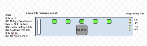
I'm building a battery pack for an efoil using an ANT bms. I want to be able to turn the battery on an off without a mechanical switch so am designing a small PCB using an Arduino. The circuit has:
The problem - With the ANT bms you only need a momentary switch to turn the BMS on and off. Therefore i need a method of sensing which state the BMS is in so the circuit does not try turn it ON when its OFF, and OFF when its ON. If the BMS switched positive, i could measure the output voltage as the signal, but since the BMS switches ground it has me stumped.
I could get around all of this by using UART, but i haven't seen a decent example this online, so think it might be above me skill level.
any advice would be much appreciated!
thanks
- 5 leds for voltage display,
- Voltage divider to measure pack voltage
- A hall effect sensor as the input to turn the battery on and off using an external magnet.
- Optoisolator to switch the BMS on and off.
- A piezo speaker
- A water ingress sensor.
The problem - With the ANT bms you only need a momentary switch to turn the BMS on and off. Therefore i need a method of sensing which state the BMS is in so the circuit does not try turn it ON when its OFF, and OFF when its ON. If the BMS switched positive, i could measure the output voltage as the signal, but since the BMS switches ground it has me stumped.
I could get around all of this by using UART, but i haven't seen a decent example this online, so think it might be above me skill level.
any advice would be much appreciated!
thanks