Hello everyone,
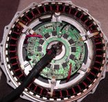
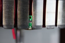
please help me to identify the hall sensors in a Bionx hub motor (see picture).
I bought the motor on ebay as "not working", i want to build an own controller for it.
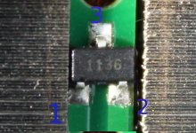
It looks similar to e.g. Honeywell SS361RT (pls. google for the datasheet).
I measured resistance between the pins of 2 sensors on the circuit board:
R(pin1-pin1) = 100 Ohm
R(pin2-pin2) = infinity
R(pin3-pin3) = 100 Ohm
R(pin3-GND) = 50 Ohm
Thus, I assume following pin configuration of the device:
pin1 - Vcc (power supply)
pin2 - output signal
pin3 - GND
I applied 10 V between pin1 and pin3 and measured about 0 V to 3 mV between pin2 and pin3 while moving the sensor between 2 magnets. Isn't this output voltage too low?
Did someone handle with this sensors?
please help me to identify the hall sensors in a Bionx hub motor (see picture).
I bought the motor on ebay as "not working", i want to build an own controller for it.
It looks similar to e.g. Honeywell SS361RT (pls. google for the datasheet).
I measured resistance between the pins of 2 sensors on the circuit board:
R(pin1-pin1) = 100 Ohm
R(pin2-pin2) = infinity
R(pin3-pin3) = 100 Ohm
R(pin3-GND) = 50 Ohm
Thus, I assume following pin configuration of the device:
pin1 - Vcc (power supply)
pin2 - output signal
pin3 - GND
I applied 10 V between pin1 and pin3 and measured about 0 V to 3 mV between pin2 and pin3 while moving the sensor between 2 magnets. Isn't this output voltage too low?
Did someone handle with this sensors?