Headway Group Purchase

JG, the current tracks across that underside are built up to carry the current from the shunt to the source legs on the FETs, the white foam sleeve surrounds a polyfuse which is set inside the pack to provide thermal protection from overheating. you can mount that polyfuse in your controller with some fine wire, 24 gauge or so, and run the jumper over to the controller from the pack, and if the controller overheats, it will shut down the battery at the source. if you can slide the sleeve off, it will have the temp stamped on the case, like this one from a tool pack. i think.
 

Attachments

  • log rounds and polyswitch 004.jpg
    log rounds and polyswitch 004.jpg
    49.9 KB · Views: 2,745
trying to fit the 48V 20Ahr on the bike .......

3363406489_f9d595fcd3_b.jpg
 
I have just ordered two 10ah 36v packs each with its own headway BMS .

What I would like to do it wire the packs so with the flick of a switch I can run 36v 20ah extended range or 72v 10ah fast speed.

Is this as simple as I am thinking it is?

Kurt.
 
Kurt said:
I have just ordered two 10ah 36v packs each with its own headway BMS .
What I would like to do it wire the packs so with the flick of a switch I can run 36v 20ah extended range or 72v 10ah fast speed.
Is this as simple as I am thinking it is?
Kurt.

It can be done. You either need a very high current rated DC switch or contractors. Contractors might be the way to go if you want to flick a switch on the handlebar on the fly. The main concern are switch contacts welding themselves together.
 
kurt should just wire it up as a 72V series pack. richard has a thread somewhere on how you put a zener diode in parallel to protect the BMS that shuts off, but i think all the parts are rated for 75V inside the BMS, so you could likely get away with running without a diode. but not certain.
 
My 48 volt 20Ahr pack has 5 Black negative wires. 1 small for the charger.


Does one really need both of the heavy wires going to the controller from the
BMS ? pack to BMS ??
 
JG, the charger wire- from the BMS and a wire directly from the positive terminal of the battery go together to the charging plug, the 4 black 16AWG wires can be spliced together to a 10AWG stranded to handle the current to the controller, same for the positive leads, with a circuit breaker or fuse inline, carry extra fuses if you use them. the connection across the center, between the first 24V of your pack and the last 24V needs to be connected by a large cable, 10AWG too, with lugs or you could actually solder the connecting stranded directly to the 2P link. but since it may be a 4 hole plate, you have to cut the plate into 2 pieces i guess. the sense wire only needs to attach on one side of the cable since they will all be at the same potential on that series link. solder all the connections for maximum capacity without heat.
 
Thanks .... how do I solder without heat ??

dnmun wrote:solder all the connections for maximum capacity without heat.


I think What Dnmun meant by that was if you solder all the connections they can can carry a lot more current without getting hot because of resistance. If you do a bad crimped connection it can become a high resistance point and will heat up.

I think headway use multiple thin wires on there BMS rather than single thick wires because it makes it easier to solder the thinner wires to the MBS board and perhaps a little easier to manage/rout the thinner cables yet they can still handle high amps.

You should use all the wires that are there especially if you are going to suck high amps from your pack.
Kurt
 
Thanks ... got it

I notice on the new case / pack they do not use soldered connections on the bms wires ... I have had 2 come undone

file.php
 
you have 2 broken connections where the lug and the sense wire connect? or does the sense wire get soldered right onto the plate with 4 holes? this easy rider is gonna be a pretty elegant ride, you coulda actually put both batteries on there, that is a huge shelf. you found a plastic tray to fit or cut one from another tray? really nice.
 
The sense wires are soldered to the plate .. but the wire is very thin to solder ... think I will use a ohm meter to check all the BMS wires

had to split the pack to get it to clear the seat and to balance the weight. had 4 SLA's on there before

bought the trays at Target after looking in every tupperware section in town
 
Do the battery packs stay cool or do they heat up while discharging or charging ? In other-words do I want to vent my battery boxes or can I pack them with dens foam to protect them from road shock ?
also someone talked about putting a fuse in between battery pack and controller can I get a bit more info on what , and where do I want to install such a fuse ? Again thanks for the help!
On a prev. page someone talked about using more hot melt to glue the sells together, my 48v pack has some loose ones as well and I think using silicon caulk might do the job as good or better it will stay more flexible, any opinion ?
Felix
 
What about the problem with the loose screws ? is it ok to lacquer them ? what about look tight, some one asked this earlier ?
most of my screws on both packs are not quite tight ?
Thanks Felix
 
A 10ah pack will stay cool on a 20amp controller.. but with a 40 amp controller they will get warm if you push them hard up hills...

Hot glue will be a stiffer bond than silicone.. personal preference on hot glue

the BMS acts as a fuse in a way, protecting over current, over voltage, over discharge etc... adding a fuse can only be a good thing, but not 100% required imo.

Tighten loose screws, but don't go ape shit on them.. a proper torque value would be nice to have.. Victoria?

The BMS will get warm/hot during charging ( or the end of charge to be more specific ) , allowing a method to let the bms cool would be a good desing idea. :wink:
 
Capripower" someone talked about putting a fuse in between battery pack and controller can I get a bit more info on what said:
I was going to put a 30 amp fuse and on/off switch between the pack + and controller
 
I just received two more headway 10ah 36v packs with bms and charger.The chargers that come with the latest pack puts out a little more voltage than the last one they sent with my old pack and finish charging at 43.9v.

What I am not to sure about is the little bms that came with each pack when the packs were charging the resistors down the bottom of the bms and the 12 little black components above them got quite hot .Not smoking hot but just hot to touch. My other big headway BMS on my old pack didn't get hot at all during charging.Is this ok?

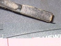
The other thing is the 4 fets up the top of the bms two each side of the little aluminium block are (P75NF75) CCOUY 6 MAR 645 not sure if this is good or bad ?
I am not sure what the BMS is rated at my other one is 60A. perhaps this one is 30A not sure. I know the other big headway BMS I have can handle two p36v packs connected to make 72v. I hope this bms can can to?

My questions are a bit silly but I don't know much about the BMS.

Oh by the way, if anyone in Australia is looking for a headway pack I got them for $260 US or $399AU each with chargers and bms posted to my door from EV power Australia took a couple of days postage from WA and were packaged very well with lots of foam around the packs.

Kurt
3381550364_1db271e975.jpg

3380729827_dd0143522b.jpg

3380729711_8d85a7c2e5.jpg


edit. After feeling both Bms boards only one of them has the hot resistors the others are only warm and looking at both bms boards the resistors look a little different on each board. They have the same number 470 on them but the one on the left is the one that gets hot.The one on the right is now completely cold.From the little I know about a BMS I am guessing the left pack is more out of balance and the resistors are sorting this out and that's what the heat is?

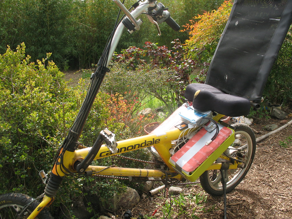
I also gave one pack a load test with my 5304 48a controller . i could load the bms up to around 36A before it would cut out.I plan on using them on my wife's bike with a 25a controller so should be ok . I wouldn't mind running both packs together to make a 20ah pack just to give the battery's a easy life and hopefully last longer as they wont be discharged as deeply.

3381723852_2b6e583236.jpg
 
Kurt said:
Oh by the way, if anyone in Australia is looking for a headway pack I got them for $260 US or $399AU each with chargers and bms posted to my door from EV power Australia took a couple of days postage from WA and were packaged very well with lots of foam around the packs.

Thats a pretty good deal for Australians. US$21.66 per cell is only a couple dollars more than $18 per cell direct from Headway without the risk of a wire transfer to a Chinese bank and the large postage cost. Its interesting that they dont advertise headway batteries on their website? Just PSI, Thundersky and ping type 2C pouches. How did you arrange the purchase? Did they import them at your request?

http://www.ev-power.com.au/
 
Thats a pretty good deal for Australians. US$21.66 per cell is only a couple dollars more than $18 per cell direct from Headway without the risk of a wire transfer to a Chinese bank and the large postage cost. Its interesting that they dont advertise headway batteries on their website? Just PSI, Thundersky and ping type 2C pouches. How did you arrange the purchase? Did they import them at your request?


Go to products on the web page then go to lifepo4 battery's.The 2nd battery down I spotted the packaging as headway .That crappy mat black cardboard paper and clear tape. I gave them a phone call and asked if they were headway cells and if they were the blue gen2 kind. As I expected they were so I ordered two of them. They have them in stock ready to go. local postage was also nice.

That $21.60 US is actually about $23 US as the exchange rate is jumping all over the place but including the bms charger and postage.

Kurt.
 
interesting stuff Kurt, thanks for keeping us in the loop.

The price IS good and I hope it keeps going down! :D

I can see they are tabbed and not screw type, as long as you have no bad cells or don't need to reorganise them at any point then it's probably a good thing as the overall package is a bit smaller that way.

So the packs trip the overcurrent protection at 36A each? That makes them good for ~1.44kW max discharge each hot off the charger.

What does your first headway 36v20Ah pack trip at? I'm very interested to find out what mine will trip on, hopefully I can determine it through testing soon.

As for your BMS getting hot, I haven't noticed mine hot at all during charging. Your guess about cell balancing makes sense to me but hopefully an electronics expert will hop on the thread and clue us all in.
 
Only one of the packs bms is getting hot and is still on the charge now and bms is still hot.

The Bms on my first 20ah pack has never tripped from over current. I cant make it trip with my 5304 and 48a controller no matter what I do.I am guessing its around 60A.

The bms on the 10ah packs looks a bit wimpy the bms on my first 20ah pack is a beast of a thing.

but looking at the 36ish Amp trip point of the 10ah packs that's 3.5c so its not to bad.

Kurt.
 
kurt was right. his old pack most likely was always in balance so the charge shut off soon after the shunts started carrying current. the new pack took longer to balance, so the shunts got hot in the meanwhile. the cells that filled first had the hottest shunt, and last one had the coldest shunt.

the tab type cells will be easy to repair. just cut out the old one with scissors and solder in the new one on the tab left behind. the replacement cells have a tab welded on them so all you do is fit and solder back in place. maybe even easier than the screw tops, since in those you would have to loosen the plate and all four screws, plus it fits between your knees when it is just the tab type, doesn't it? might be too long.

your original BMS was different because it was a 16S BMS but only 12 channels were populated. this has different pcb, likely different number of output FETS and charging FET. smaller too. does it have the polyfuse on the underside too?
 
your original BMS was different because it was a 16S BMS but only 12 channels were populated. this has different pcb, likely different number of output FETS and charging FET. smaller too. does it have the polyfuse on the underside too?

There is the same temp fuse/ poly fuse on the underside as my other bms.

There is only 4 output fets on the little bms type (P75NF75) CCOUY 6 MAR 645

I measured all 12 cells on the pack with the hot bms. I found 10 cells at 3.7v and two cells at 3.5v
 
I just recieved a 24v20aH Headway battery pack, and I'm having problems with the battery cutting out when using a Cyclone 500W motor. When I gradually add brake load on the motor the battery cuts out at ~25A, so I don't think its due to the motor controller, but it may due to the BMS. Has anyone seen this type of problem?
 
Back
Top