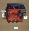
((Help me please!! alternator delta conversion as a motor))

kejanostra said:
Hello Parabellum, before welding the wire, and burning out the servo tester!
To see on picture, the rear view of the card servo tester, because I hesitate between 1 or 2(middle),
to weld the wire jumper on brooch "Signal" IN, in 1 or 2 of the potentiometer.
I know that it is necessary to delete the button potentiometer, you worry not.

Here is the tread:
http://endless-sphere.com/forums/viewtopic.php?f=28&t=12196&start=15#p313413
Here is the corrupt picture you can not see any more:
file.php

Your Servotester works same way, I modified 1 of those as yours, just to lazy to stand up and make a picture. :)
 

Attachments

  • 123.jpg
    123.jpg
    28.2 KB · Views: 2,038
parabellum said:
kejanostra said:
Hello Parabellum, before welding the wire, and burning out the servo tester!
To see on picture, the rear view of the card servo tester, because I hesitate between 1 or 2(middle),
to weld the wire jumper on brooch "Signal" IN, in 1 or 2 of the potentiometer.
I know that it is necessary to delete the button potentiometer, you worry not.

Here is the tread:
http://endless-sphere.com/forums/viewtopic.php?f=28&t=12196&start=15#p313413
Here is the corrupt picture you can not see any more:
file.php

Your Servotester works same way, I modified 1 of those as yours, just to lazy to stand up and make a picture. :)


Hello,
I have just welded at the moment where you send the picture,I welded the jumper on "S" IN, to middle (+) place potentiometer.
Thank you. :wink:
 
Handle effect hall works not! And ESC gets into a panic of beep!,
for my opinion, that is the handle is 12V, and the servo tester gives between 4,8V and 6V, BEC of the ESC gives 5V 3A, thus average of 5V to work,
but handle asks too much, or, if it is necessary connected the "S" IN, to the (+) location potentiometer, then my case, the (+) is situated in position 3 (on picture I posted higher), I looked the (+) with my multimeter.
 
kejanostra said:
Handle effect hall works not! And ESC gets into a panic of beep!,
for my opinion, that is the handle is 12V, and the servo tester gives between 4,8V and 6V, BEC of the ESC gives 5V 3A, thus average of 5V to work,
but handle asks too much, or, if it is necessary connected the "S" IN, to the (+) location potentiometer, then my case, the (+) is situated in position 3 (on picture I posted higher), I looked the (+) with my multimeter.
1) Throttle is only doing resistor work in this situation. So ESC in panic beep is strange?
2)Do you really know throttle outputs? Do not look at the colors, they are random! I got a throttle that was Red+ White- Green signal.
If you have tester/meter find out what wiring throttle has. If you connect + and- signall should vary between .5-4.5V by twisting action.
 
parabellum said:
kejanostra said:
Handle effect hall works not! And ESC gets into a panic of beep!,
for my opinion, that is the handle is 12V, and the servo tester gives between 4,8V and 6V, BEC of the ESC gives 5V 3A, thus average of 5V to work,
but handle asks too much, or, if it is necessary connected the "S" IN, to the (+) location potentiometer, then my case, the (+) is situated in position 3 (on picture I posted higher), I looked the (+) with my multimeter.
1) Throttle is only doing resistor work in this situation. So ESC in panic beep is strange?
2)Do you really know throttle outputs? Do not look at the colors, they are random! I got a throttle that was Red+ White- Green signal.
If you have tester/meter find out what wiring throttle has. If you connect + and- signall should vary between .5-4.5V by twisting action.


After a test of continuity with multi meter:
Here is how is presented points (+), (-), (S) of potentiometer on the card servo tester (not similar as other servo tester).
And normally, he is necessary to put the jumper between the "S" of handle , and the "+" of potentiometer, it is good?
Look my picture:
IMAG1876.png
 
kejanostra said:
parabellum said:
kejanostra said:
Handle effect hall works not! And ESC gets into a panic of beep!,
for my opinion, that is the handle is 12V, and the servo tester gives between 4,8V and 6V, BEC of the ESC gives 5V 3A, thus average of 5V to work,
but handle asks too much, or, if it is necessary connected the "S" IN, to the (+) location potentiometer, then my case, the (+) is situated in position 3 (on picture I posted higher), I looked the (+) with my multimeter.
1) Throttle is only doing resistor work in this situation. So ESC in panic beep is strange?
2)Do you really know throttle outputs? Do not look at the colors, they are random! I got a throttle that was Red+ White- Green signal.
If you have tester/meter find out what wiring throttle has. If you connect + and- signall should vary between .5-4.5V by twisting action.


After a test of continuity with multi meter:
Here is how is presented points (+), (-), (S) of potentiometer on the card servo tester (not similar as other servo tester).
And normally, he is necessary to put the jumper between the "S" of handle , and the "+" of potentiometer, it is good?
Look my picture:
IMAG1876.png


Hello the guys!
I solved my problem, the handle works as a charm!
Thus I found my "+", "-", and "S= signal", on location of the potentiometer, and, just to connect the wires of the handle, "+ red", "- black", and "S=signal, green", directly on location of the potentiometer.
But misfortune for me, my device weld has to return its soul!
Thus I would make the welds later, I would stretch out the wires of the handle because they are really too short,
but the important and what I know now, what everything works as a charm! 8)
Here are the truths connections:
 
Just so I understand correctly, what you are showing, is, the bottom of the circuit board of the Servo Tester ? Is that correct ?

Instead of connecting to the plug in pins, you need to connect to those 1-2-3 solder points, correct ?

I want to get a few parts and try what you have shown in your success of running the altermotor.

In the beginning, you are sending 12V into the altermotor, or higher voltage, and approximately 6V into the rotor for field control, correct ?

Thanks for showing everything you have done. I need to make up 3-4 of these altermotors, to run my shop tools, and, these look cheap enough, compared to buying brushed DC motors, or, needing expensive (compared to your system) controllers for brushless motors.
 
Harold in CR said:
Just so I understand correctly, what you are showing, is, the bottom of the circuit board of the Servo Tester ? Is that correct ?

Instead of connecting to the plug in pins, you need to connect to those 1-2-3 solder points, correct ?

I want to get a few parts and try what you have shown in your success of running the altermotor.

In the beginning, you are sending 12V into the altermotor, or higher voltage, and approximately 6V into the rotor for field control, correct ?

Thanks for showing everything you have done. I need to make up 3-4 of these altermotors, to run my shop tools, and, these look cheap enough, compared to buying brushed DC motors, or, needing expensive (compared to your system) controllers for brushless motors.


Hello Harold in CR,

If you want to have this conversion just as engine tool, then not need to connect as I make on 1, 2, 3, but just to connect the tester of servo (exit) towards the ESC controller, so you can played the speed of your engine tool.

Then, at the moment I feed (rotor and stator) with 12V battery car, (in daytimes, I go fed just the rotor with lower tension, to have more speed, and I would mean saying if he works later).
Then, if you take an alternator 100A (for example), you have to take a higher ESC controller (for example: 120A), and according to the ESC controller, he can be fed between 2S in 6S, thus 7V in 22,2V.

For your case, he would be ideal to take supply PC 12V, because your engine tool will be fixed, and you will can even fed several engine tool (by remaining reasonable).
You need:
1 alternator, for example: 70A)
1 ESC 80A, with BEC (to connect servo tester), for example also, link good seller:http://cgi.ebay.fr/ws/eBayISAPI.dll...eName=STRK:MEWNX:IT&_trksid=p3984.m1439.l2649
1 tester of servo, link good seller:http://cgi.ebay.fr/ws/eBayISAPI.dll...eName=STRK:MEWNX:IT&_trksid=p3984.m1439.l2649
1 supply PC computer (110V/12V).

I would return in a few days, to make a tutoriel explanation with picture. :wink:
 
Actually, I would like variable speed for different tools. Drill press, possibly milling machine, cut off machine for metal, power hacksaw, lathes, both wood and metal, etc.

I am planning total DC electricity in my house and part of my shop. Commercial power is not really stable or totally reliable, here. More than once, I was cutting wood on a table saw, and, the power cuts out, then, back on, etc. Could have easily lost fingers or more.
 
Video does not work for me.

If you just used the servo tester, that would also provide speed control, correct ? I only need a twist control for something I want to ride, correct ?
 
Harold in CR said:
Video does not work for me.

If you just used the servo tester, that would also provide speed control, correct ? I only need a twist control for something I want to ride, correct ?


YES, exactly!
For you, is just enough the tester of servo and the ESC for make worked the alternator/engine, so, you will can played the speed with the rotating button.
 
Sorry for the video, I had forgotten to configure available for "whole world" in YouTube.

Otherwise, I am not an expert in electronics, I have a last thing to be settled for this conversion, then, I wish lowered the tension of the rotor of 12V, in approximately 1,5V-4V to make run more hardly.
Thus I made a bridge divisor of tension, but when I connect him of the battery 12V and on rotor, I have 0,02V on rotor with my multimeter?!
And nevertheless, if I connect the bridge divisor of tension on 12V battery, without connecting on the rotor, on the wires I obtain 3V, then I understands not!
My question, I can used this component "adjustable voltage converter" to feed the rotor as I wish?

Link:http://www.ebay.fr/itm/QZO-DC-DC-Bu..._Measurement_Equipment_ET&hash=item233b1d4271

Thank You.
 
kejanostra said:
Sorry for the video, I had forgotten to configure available for "whole world" in YouTube.

Otherwise, I am not an expert in electronics, I have a last thing to be settled for this conversion, then, I wish lowered the tension of the rotor of 12V, in approximately 1,5V-4V to make run more hardly.
Thus I made a bridge divisor of tension, but when I connect him of the battery 12V and on rotor, I have 0,02V on rotor with my multimeter?!
And nevertheless, if I connect the bridge divisor of tension on 12V battery, without connecting on the rotor, on the wires I obtain 3V, then I understands not!
My question, I can used this component "adjustable voltage converter" to feed the rotor as I wish?

Link:http://www.ebay.fr/itm/QZO-DC-DC-Bu..._Measurement_Equipment_ET&hash=item233b1d4271

Thank You.
What current flow you get on 12V? If your current draw is less then this converter delivers you can use it, but look for same converter with black heat sink attached on the back.
 
parabellum said:
kejanostra said:
Sorry for the video, I had forgotten to configure available for "whole world" in YouTube.

Otherwise, I am not an expert in electronics, I have a last thing to be settled for this conversion, then, I wish lowered the tension of the rotor of 12V, in approximately 1,5V-4V to make run more hardly.
Thus I made a bridge divisor of tension, but when I connect him of the battery 12V and on rotor, I have 0,02V on rotor with my multimeter?!
And nevertheless, if I connect the bridge divisor of tension on 12V battery, without connecting on the rotor, on the wires I obtain 3V, then I understands not!
My question, I can used this component "adjustable voltage converter" to feed the rotor as I wish?

Link:http://www.ebay.fr/itm/QZO-DC-DC-Bu..._Measurement_Equipment_ET&hash=item233b1d4271

Thank You.
What current flow you get on 12V? If your current draw is less then this converter delivers you can use it, but look for same converter with black heat sink attached on the back.


I want just, from 12V battery, to go out 3V for the rotor (3A).
What component I can take to make that?
 
kejanostra said:
parabellum said:
kejanostra said:
Sorry for the video, I had forgotten to configure available for "whole world" in YouTube.

Otherwise, I am not an expert in electronics, I have a last thing to be settled for this conversion, then, I wish lowered the tension of the rotor of 12V, in approximately 1,5V-4V to make run more hardly.
Thus I made a bridge divisor of tension, but when I connect him of the battery 12V and on rotor, I have 0,02V on rotor with my multimeter?!
And nevertheless, if I connect the bridge divisor of tension on 12V battery, without connecting on the rotor, on the wires I obtain 3V, then I understands not!
My question, I can used this component "adjustable voltage converter" to feed the rotor as I wish?

Link:http://www.ebay.fr/itm/QZO-DC-DC-Bu..._Measurement_Equipment_ET&hash=item233b1d4271

Thank You.
What current flow you get on 12V? If your current draw is less then this converter delivers you can use it, but look for same converter with black heat sink attached on the back.


I want just, from 12V battery, to go out 3V for the rotor (3A).
What component I can take to make that?
You must measure consumption of the rotor with something like multimeter. In higher V on rotor you get higher torque and lower speed, on lowerV lover torque and higher speed. Consumption of rotor is higher on higher voltage. Your stepdown converter should be capable to deliver the current on highest planned Voltage.
 
You must measure consumption of the rotor with something like multimeter.

Could you please explain how to do this ? I have ruined 2 VOM's trying to get Amp readings, under 8 Amp's.
 
You must measure consumption of the rotor with something like multimeter. In higher V on rotor you get higher torque and lower speed, on lowerV lover torque and higher speed. Consumption of rotor is higher on higher voltage. Your stepdown converter should be capable to deliver the current on highest planned Voltage.[/quote]


Yes Parabellum,
I understood for rotor more "couple", with high tension, and more "speed", with lower tension.
But I never have make of taking consumption with a multimeter, I make basic things in electricity, and, I am a "quiche" in this electric domain. :mrgreen:
But I was able to read that, the rotor at need enters 0,5A until 3A Maximum, and the converter step-down transformer can supply until 3A maximum also, then it should be good, in more on the previous one pages, on videos I posted, a guy in used this converter, that's why I ask all the same before buying.
 
Thus I took the value of the current ampere for the rotor, and through 12V battery, in rest he gives 3A, and 2,85A in full gas.
Connect everything, then switch on and put on position 10A, and conversely.
I made the test " Ampèrage " as on the sketch, and work direct! :wink:

IMAG1880.png
 
kejanostra said:
Thus I took the value of the current ampere for the rotor, and through 12V battery, in rest he gives 3A, and 2,85A in full gas.
Connect everything, then switch on and put on position 10A, and conversely.
I made the test " Ampèrage " as on the sketch, and work direct! :wink:

It should work then, go conservatively from lower V up and observe the temperature, then set absolute limit. I suppose, even with cooling plate, 3A will be hard on that tiny circuit. Do not expect more then 2A for reliability.
 
parabellum said:
kejanostra said:
Thus I took the value of the current ampere for the rotor, and through 12V battery, in rest he gives 3A, and 2,85A in full gas.
Connect everything, then switch on and put on position 10A, and conversely.
I made the test " Ampèrage " as on the sketch, and work direct! :wink:

It should work then, go conservatively from lower V up and observe the temperature, then set absolute limit. I suppose, even with cooling plate, 3A will be hard on that tiny circuit. Do not expect more then 2A for reliability.


You want to say, that if I lower V on rotor, Ampere will also fall, and thus it goes warmed higher?
I have no thermometer to take the temperature (I am not equipped as expert) :lol:
But, what genre of dissipator I have to take to put on " converter step-down transformer ", and how make hold on him later?
 
Back
Top