((Help me please!! alternator delta conversion as a motor))

kejanostra

100 W
Joined
Jun 20, 2014
Messages
110
Hello to everybody!

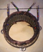
I have a problem to be solved concerning the conversion of my alternator 70A as a motor, look at the picture.
I want to put in triangle coupling my stator, but he has 6 wires double! Then how to make,
I tried several connection and he does not work!

View attachment 2


Here are all what I have for this conversion.
I also have a battery 12V car but not present on picture.

imag1859.gif


I have make as here, but nothing! No functioning.

imag.gif


That is what I make:

I know that I have to have 3 phases of the stator ( A-B-C) and in delta, then connect in 3 wires of the controller rc,
and I connect + and - of the controller rc on battery 12V.
Then, I delete the regulator on the support coal, and I connect 2 wires on coal/rotor towards the battery 12V,
and I connect the small wire ( 3 wires) of the controller rc towards the out of the tester servo.
It is very like that?
But nothing works!

Thank you for your help.
 
I am no expert, but, it seems to be double wound coils? 2 wires for each coil for higher amp rating.

If this is correct, here is a link reference to how to connect either Y or Delta for the 3 phase winding.

LINK

Hope this helps and keep in touch. There are threads on this forum about motoring an Alternator, but, the results were never posted.
 
Harold in CR said:
I am no expert, but, it seems to be double wound coils? 2 wires for each coil for higher amp rating.

If this is correct, here is a link reference to how to connect either Y or Delta for the 3 phase winding.

LINK

Hope this helps and keep in touch. There are threads on this forum about motoring an Alternator, but, the results were never posted.


Thank you for the link Harold :wink:

Thus, if I understands well!
Here is my plan for my three phases, A, C, E :

imag1835.jpg

image 1.jpg

But, for the three others wires (B, D, F) :? ,
I owe connected together A and D, B and E, C and F,
or then just connected together the wires (B, D, F)?

Thank you.
 
The next diagram below the one you show in your last post, shows the Delta Wye connections.

For Delta you have 6 ends, in your case, 6 DOUBLE ends. You want to make a series or triangle shape using the 3 coils. SO, take one end of the first coil and connect it to the next coil , then, take that second coil and connect it to the first coil, so you have connected all 3 coils in SERIES.

Now, I'm not sure if the winding rotation of each coil comes into play, here. In motor winding, it does. One coil is wound clockwise, the next counter clockwise, etc., etc., etc.

So, I would think, if you can tell which sets of coil windings are wound the same way, that's the way I would connect them.

Then, you run your phase wires from the Connection points of the three coil connections, for 3 phase.

I hope I have this correct. I want to do the same thing, as soon as I get my magnets in a couple of weeks. I want to make a magnetically energized rotor, so, no outside voltage needed, for the slip ring- field coil inside the rotor claws.
 
Harold in CR said:
The next diagram below the one you show in your last post, shows the Delta Wye connections.

For Delta you have 6 ends, in your case, 6 DOUBLE ends. You want to make a series or triangle shape using the 3 coils. SO, take one end of the first coil and connect it to the next coil , then, take that second coil and connect it to the first coil, so you have connected all 3 coils in SERIES.

Now, I'm not sure if the winding rotation of each coil comes into play, here. In motor winding, it does. One coil is wound clockwise, the next counter clockwise, etc., etc., etc.

So, I would think, if you can tell which sets of coil windings are wound the same way, that's the way I would connect them.

Then, you run your phase wires from the Connection points of the three coil connections, for 3 phase.

I hope I have this correct. I want to do the same thing, as soon as I get my magnets in a couple of weeks. I want to make a magnetically energized rotor, so, no outside voltage needed, for the slip ring- field coil inside the rotor claws.


Harold, please :lol: ,
make me a plan on this picture:
imag1835.jpg
Because as we say, an picture is better that a long speech :wink:
Yes I wish to make a delta 3 phases.
Thank you.
 
kejanostra said:
Harold in CR said:
The next diagram below the one you show in your last post, shows the Delta Wye connections.

For Delta you have 6 ends, in your case, 6 DOUBLE ends. You want to make a series or triangle shape using the 3 coils. SO, take one end of the first coil and connect it to the next coil , then, take that second coil and connect it to the first coil, so you have connected all 3 coils in SERIES.

Now, I'm not sure if the winding rotation of each coil comes into play, here. In motor winding, it does. One coil is wound clockwise, the next counter clockwise, etc., etc., etc.

So, I would think, if you can tell which sets of coil windings are wound the same way, that's the way I would connect them.

Then, you run your phase wires from the Connection points of the three coil connections, for 3 phase.

I hope I have this correct. I want to do the same thing, as soon as I get my magnets in a couple of weeks. I want to make a magnetically energized rotor, so, no outside voltage needed, for the slip ring- field coil inside the rotor claws.


Harold, please :lol: ,
make me a plan on this picture:
View attachment 1
Because as we say, an picture is better that a long speech :wink:
Yes I wish to make a delta 3 phases.
Thank you.


I does not maybe understand, but sorry, I would understand better with a plan I think.
then it is like that?


Thank you for your support :wink:
 
Harold in CR said:
Sorry for the delay. PM sent.


No worries Harold, you are already kind of you interest in my problem.
Thank you, and I you will give my result.
 
Harold in CR said:
Sorry for the delay. PM sent.


I already have make this connection, but not work not unfortunately.
There is my problem, to see my image you will see.

Image 8.jpg
 
I can't tell about your last image, but, it's nothing like I told you to try.

Did you locate both ends of all 3 winding coils? They are double, so, you need to get continuity from 2 ends, and that makes 1 winding coil.

Then, connect those ends to make a "Triangle" shaped circuit. Then, connect your phase leads to each connection join of the 3 sets of windings.

In your Pm to me, I did not see any Diodes, so, you must have bypassed those. You do NOT want diodes or a "rectifier" (AC to DC voltage) in this system.
 
Harold in CR said:
I can't tell about your last image, but, it's nothing like I told you to try.

Did you locate both ends of all 3 winding coils? They are double, so, you need to get continuity from 2 ends, and that makes 1 winding coil.

Then, connect those ends to make a "Triangle" shaped circuit. Then, connect your phase leads to each connection join of the 3 sets of windings.

In your Pm to me, I did not see any Diodes, so, you must have bypassed those. You do NOT want diodes or a "rectifier" (AC to DC voltage) in this system.


Hello Harold!
Then, here is an picture or we can see 6 wires (double) of my stator.

Yes, i located and tested the extremities of the wires with my multimeter in mode "Beep sound" for continuity, and, the crossed wires together (on picture) they give the " beep sound ",
then how connected later for a triangle?
You speak about a diode, but where she settles down, and to what she is of use ?
I just wish running the alternator as an motor, and not generate some electricity with him.
Because the people that I saw (on YouTube) used this conversion, just with the same material as me.
Thank you.
 
Several people on this forum seem to have already made this conversion,
but nobody reacts! :cry:
 
If those pairs of wires are identified correctly, and, you connect from one to the other to the other, you have that Delta "Triangle". Connect a phase wire to each connection you have connected the pairs of wires. You will need a throttle of some sort. I am not familiar with RC devices.
 
Harold in CR said:
If those pairs of wires are identified correctly, and, you connect from one to the other to the other, you have that Delta "Triangle". Connect a phase wire to each connection you have connected the pairs of wires. You will need a throttle of some sort. I am not familiar with RC devices.


Connected as on the picture?
Where without the green arrow of below?
imUU.jpg
 
OK :!:
I notice that nobody realized this experience,
especially with a stator 6 wires doubled as me,
thus, I am going to make other combinations in my corner.
 
I have been working all day, so, only just now able to offer assistance.

Yes, IF you have connected the 6 sets of 2 wires each, in 3 groups of wires, THAT is your Delta . YES, the 3 lines you put in that last photo is the correct way to connect the phase wires.
 
If colors correspond to IN-OUTs of phases, then ABC are your ESC phase connection points.
file.php
 

Attachments

  • imag1835.jpg
    imag1835.jpg
    81.3 KB · Views: 3,560
Harold in CR said:
I have been working all day, so, only just now able to offer assistance.

Yes, IF you have connected the 6 sets of 2 wires each, in 3 groups of wires, THAT is your Delta . YES, the 3 lines you put in that last photo is the correct way to connect the phase wires.


Hello Harold,

Thus, if I seized well, 3 arrow (red) give my 3 exits (A-B-C), thus my 3 phases to connect towards my controller, and, 3 arrows (green), must be together connected?
 
parabellum said:
If colors correspond to IN-OUTs of phases, then ABC are your ESC phase connection points.
file.php


Hello parabellum,
thank you,
but, I have already made this connection, and his do not work.
Look the picture.
Image 8.jpg
 
Yes, I believe you have them correct to connect color to color.
 
kejanostra said:
Hello parabellum,
thank you,
but, I have already made this connection, and his do not work.
Look the picture.
Sure your ESC and servotester are good. Do you have BLDC motor to try them out. Things sometimes come DOA from HK or you may have damaged this tinny unprotected ESC by wrong connection without noticing that.
 
parabellum said:
kejanostra said:
Hello parabellum,
thank you,
but, I have already made this connection, and his do not work.
Look the picture.
Sure your ESC and servotester are good. Do you have BLDC motor to try them out. Things sometimes come DOA from HK or you may have damaged this tinny unprotected ESC by wrong connection without noticing that.

Hello!
And thank you for the effort.
No, I have no BLDC.
And with certain connections, the ESC emits the " beeps " in the starting up, thus I suppose that it works, and the tester servo ignites correctly also.
But, I was right to delete the regulator on the support of coal?
I also deleted the bridge of diode, and I connect 2 wires who come from the rotor, as well as 2 wires who come from the controller on the 12V of the battery car.
Would another controller be needed maybe another for the rotor?
Widodo on this forum, made this conversion, I sent a mp to him, but without answer at the moment.
 
Back
Top