
kejanostra
100 W
- Joined
- Jun 20, 2014
- Messages
- 110
A small conversion for cycle which costs cheap! MDR :lol:
[youtube]dzfDbZY8Fuo[/youtube]
[youtube]dzfDbZY8Fuo[/youtube]
Skalabala said:You need 200A rc controller to be able to pull 30A+-
Are you planning to use the alternator for an electric vehicle?
Skalabala said:Its going to be expensive to make enough power with an alternator for an EV
Maybe just go with a brushed motor and controller?
Do you need to use the alternator or does it just need to be a cheap scooter?
parabellum said:Wait a moment! Why do you have your servo tester connected on IN side? PWM signal for the ESC comes from OUT side! + and - are shared by both sides.
You can try to run other BLDC motor, old hard drive main motor for examplekejanostra said:parabellum said:Wait a moment! Why do you have your servo tester connected on IN side? PWM signal for the ESC comes from OUT side! + and - are shared by both sides.
YES, on my picture which I posted, PWM is on IN, but I understood later by seeing video YouTube, which PWM goes side OUT, no concern. :wink:
But in this way, not work not also.
How I can make a test for ESC, to be sure that he is good Dead?
parabellum said:You can try to run other BLDC motor, old hard drive main motor for examplekejanostra said:parabellum said:Wait a moment! Why do you have your servo tester connected on IN side? PWM signal for the ESC comes from OUT side! + and - are shared by both sides.
YES, on my picture which I posted, PWM is on IN, but I understood later by seeing video YouTube, which PWM goes side OUT, no concern. :wink:
But in this way, not work not also.
How I can make a test for ESC, to be sure that he is good Dead?
Skalabala said:
How did you accessed phase wires or this ventilator? You could take old CD or DVD rom motor as well.kejanostra said:Skalabala said:
Thank you for the link skalabala, ha ha ha :lol:
I was far from believing that this thing is possible
I knew not, now yes. :wink:
I have a hard disk, but I want not damaged because I have data inside.
I tried this test with mini ventilator 12V of pc, and it weakly turned then ESC makes beep beep....
parabellum said:How did you accessed phase wires or this ventilator? You could take old CD or DVD rom motor as well.kejanostra said:Skalabala said:
Thank you for the link skalabala, ha ha ha :lol:
I was far from believing that this thing is possible
I knew not, now yes. :wink:
I have a hard disk, but I want not damaged because I have data inside.
I tried this test with mini ventilator 12V of pc, and it weakly turned then ESC makes beep beep....
P.S. Go to any computer repair shop they will trow at you with damaged HDs and CD roms.
parabellum said:If colors correspond to IN-OUTs of phases, then ABC are your ESC phase connection points.
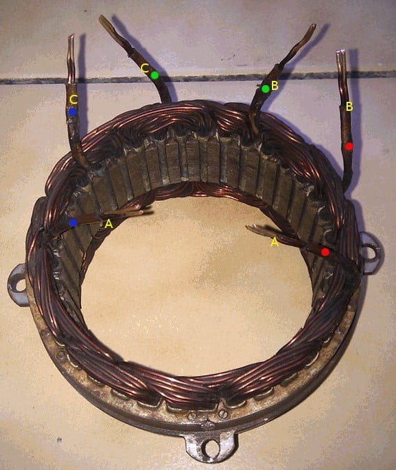
kejanostra said:parabellum said:If colors correspond to IN-OUTs of phases, then ABC are your ESC phase connection points.
Sorry but, for repeat the connection "delta" and be sure of myself!
I connect the points blue together, green together, then red together, or, A+A, B+B, C+C ?
Thank you for your patience Parabellum :wink:
PS:My magnets rotor and stator were with thickness get greasy enormous and to turn with difficulty,
but once to clean, then to sand with wire wool, so turn better, and I put a magnet on them, and magnetism better also.
I make a test after and give the result.
kejanostra said:Concerning the connection ventilator, he has 4 wires (black-, yellow +, blue, green, for the speed I think?!),
then I connected black, yellow, and blue, or green, towards 3 wires ESC.
The ventilator work weak, saccader, and ESC to emit Several beep.((((((

Nice. Glad to read it!kejanostra said:Solved 8)
parabellum said:Nice. Glad to read it!kejanostra said:Solved 8)
P.S. You know, you can connect your hall throttle to servotester, right? :wink:
parabellum said:Nice. Glad to read it!kejanostra said:Solved 8)
P.S. You know, you can connect your hall throttle to servotester, right? :wink:


Harold in CR said:So, exactly what determines the speed ? Is the servo tester adjusting the field weakening and the twist throttle adjusting the volts-amperage to the motor, all at the same time ?
Electronics is what has me baffled.
")