Salty Souls
1 mW
Hi,
I recently purchased a non working ebike and upon diagnosis it would appear that it is a hall sensor issue. However, I also have some other questions about the set up as well.
Overall Set Up
- Battery = 72v, 14.4Ah, BMS 40Ah
- Controller = 60V, 30Ah
- Hub Motor = Bafang RM G0F4.1000w (same or similair to Bafang G063 motor) 48v to 60v?
My questions are:
1. On checking the Bafang website it indicates they only make this motor in 48v to 52v. However, it is marked on the hub wheel that it is 60v (see pictures). Does this matter and if so how can I check?:


2. From different forum sites I've gotten different answers (this could also be just my lack of understanding) about the requirement to match battery v to controller v to motor v - at a minimum battery and controller v has to equal. Is this right or does it have to been within a range.
3. Related to question 2, should this set up work in terms of battery, controller and motor specs? Or does the battery have to much V for the controller and in turn the controller for the motor (assuming I can confirm if the motor is 60v or not)?
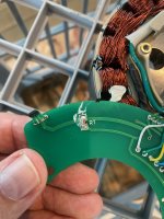
4. I've tested the motor and it would appear that the hall sensors are faulty. I ran a continuity test using a multi meter from the motor cable connection to the PCB board and it all appeared fine - so I ruled out frayed or cut motor cable. Then connected power to the motor and got different voltage responses using the multi meter from each of the hall sensors as I slowly turned the wheel.
I've tried to find a replacement PCB board but can't find it anywhere - thought it would be easier to replace the PCB board than the hall sensors. If someone knows where I could purchase the PCB board that would be great (I've looked on aliexpress, etc and Ive contacted Bafang directly)

Thanks
I recently purchased a non working ebike and upon diagnosis it would appear that it is a hall sensor issue. However, I also have some other questions about the set up as well.
Overall Set Up
- Battery = 72v, 14.4Ah, BMS 40Ah
- Controller = 60V, 30Ah
- Hub Motor = Bafang RM G0F4.1000w (same or similair to Bafang G063 motor) 48v to 60v?
My questions are:
1. On checking the Bafang website it indicates they only make this motor in 48v to 52v. However, it is marked on the hub wheel that it is 60v (see pictures). Does this matter and if so how can I check?:
2. From different forum sites I've gotten different answers (this could also be just my lack of understanding) about the requirement to match battery v to controller v to motor v - at a minimum battery and controller v has to equal. Is this right or does it have to been within a range.
3. Related to question 2, should this set up work in terms of battery, controller and motor specs? Or does the battery have to much V for the controller and in turn the controller for the motor (assuming I can confirm if the motor is 60v or not)?
4. I've tested the motor and it would appear that the hall sensors are faulty. I ran a continuity test using a multi meter from the motor cable connection to the PCB board and it all appeared fine - so I ruled out frayed or cut motor cable. Then connected power to the motor and got different voltage responses using the multi meter from each of the hall sensors as I slowly turned the wheel.
I've tried to find a replacement PCB board but can't find it anywhere - thought it would be easier to replace the PCB board than the hall sensors. If someone knows where I could purchase the PCB board that would be great (I've looked on aliexpress, etc and Ive contacted Bafang directly)
Thanks