Help with hooking up a larger motor controller to my Chinese electric truck

irpilot

1 µW
Joined
Feb 4, 2025
Messages
3
Location
Houston
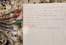
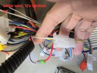
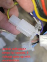
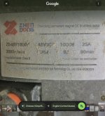
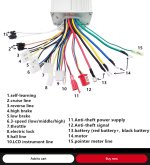
Looking for some help connecting a motor controller to my electric truck. I can't figure out what plugs go to what. I've opened up the new motor controller and found out where each wire connects on the board but I'm not any closer to getting the motor to work. ☹️
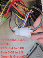
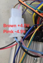
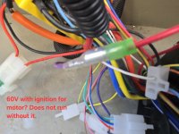
. First pic is the new controller. The rest of the pics are the wires attached to the truck from the old controller. Hopefully someone can help me out.
 

Attachments

  • 20250204_125724.jpg
    20250204_125724.jpg
    4.4 MB · Views: 12
  • 20250131_111707.jpg
    20250131_111707.jpg
    3.1 MB · Views: 11
  • 20250131_111614.jpg
    20250131_111614.jpg
    1.4 MB · Views: 8
  • 20250131_111810.jpg
    20250131_111810.jpg
    2.5 MB · Views: 8
  • 20250131_111744.jpg
    20250131_111744.jpg
    2.4 MB · Views: 8
  • 20250131_111931.jpg
    20250131_111931.jpg
    986.2 KB · Views: 11
What Make and model of the truck?
What controller is currently in the truck?
What motor is in the truck?
What is the new controller?
Is the controller the correct type?
Many light duty electric vehicles used three phase AC induction motors.
A link to the controller either sales page or the controller manufacturer page?
The more information you provide the better help you can receive.
Later floyd
 
Gotta love that totally undocumented, random color wire scheme, almost like a FU to the DIYer!

I would personally gut all the electronics attached to the controller and start with new, matched and documented components instead of try to reverse engineer that mess. Even wire for wire, signal voltages and stuff might not be compatible, it's gonna be a headache.

Another problem is that your battery might be able to output the additional amps you want... unless you've already confirmed it's overbuilt by observing max voltage drop at full throttle and saw it barely sag.
What Make and model of the truck?
What controller is currently in the truck?
What motor is in the truck?
What is the new controller?
Is the controller the correct type?
Many light duty electric vehicles used three phase AC induction motors.
A link to the controller either sales page or the controller manufacturer page?
The more information you provide the better help you can receive.
Later floyd
Thanks for the reply. I think the controller is either bad or not compatible. I'm looking at replacing it with a smaller controller (60V 2000w). I've read and watched a lot of YouTube videos on connecting controllers and it seems pretty straightforward? It looks like all the truck needs to run on the current controller are the hall motor wires(thick blue green and yellow), hall sensor wires (5 wire plug with red black blue green and yellow) , main power and ground ( thick red and black) , throttle( 3 wire plug red green and black), reverse (2 wire plug) and a single wire instrument line? The current controller also has what I assume is the the electric power lock which is hooked up to a 60v wire. I've attached a pic of the wiring for the controller I'm looking at now (last pic) and it looks like it has all the wires I need? I've read that since #8 electric lock is two wires on this controller, you just jump the one wire to the other to close the circuit?

The truck is a Meco P4
The current controller is a 60V 1000w brushless motor controller.
The motor is a 48V 1000w 25 amp permanent magnet brushless DC motor.
The new motor controller is a 48V-72V 5000W Tricycle FOC Controller, Battery Car, Intelligent Brushless Motor Controller, Electric Car. Here is the link. https://a.aliexpress.com/_mOXciEB
The truck has 5 12v lead acid batteries wired in series.
I was planning on replacing the current 48V 1000w motor with a 60V 1800w motor.
 

Attachments

  • Screenshot_20240625_081935_Chrome.jpg
    Screenshot_20240625_081935_Chrome.jpg
    255.9 KB · Views: 6
  • Screenshot_20250204_233021_Google.jpg
    Screenshot_20250204_233021_Google.jpg
    1.8 MB · Views: 7
  • Screenshot_20250204_233235_Google.jpg
    Screenshot_20250204_233235_Google.jpg
    1.8 MB · Views: 6
  • Screenshot_20250204_235733_AliExpress.jpg
    Screenshot_20250204_235733_AliExpress.jpg
    705.3 KB · Views: 6
Is your controller programmable? because you'd want to dial the amps way, way down. It's unlikely that a battery designed for 1000w will handle 5000w... ( the battery management system would probably intervene since this is way over the stock current limit )

The motor might also not be up to 5x the amps, hopefully you are not in a hilly area.
 
Also, if it's an FOC controller, then even after you wire it all up, you almsot certainly still have ot run the setup software for the controller to program it for the specific properties of your motor (magnet poles, kV, inductance, resistance, position sensor type and setup / angles, etc).

Some controllers have a good autolearn routine, but that doesnt' always work right evne on the best ones and some of them are terrible at it even with "easy" motors.

You'd have to check yoru controller's manual for exactly how to do this setup; if it's as poorly documented as some, you'll end up having to figure it out by trial and error. (if you do, please post up what you find as a "manual" to help anyone else that comes along trying to find info on that specific controller).
Ok will do. Thanks.
 
Back
Top