
HAL9000v2.0
10 kW
WOW! 

Aren't those pictures illegal for younger than 21?
Aren't those pictures illegal for younger than 21?
GGoodrum said:Hmm... The holes in Matt's drive are on the sides, so maybe these type clamps might work turned sideways, and then a plate that bolts to these and to the mount? You'd need four of these, two for each side.
What we really need is a different mount that has a built-in frametube clamp. :wink: :wink: Got any freetime yet Matt??
-- Gary
1clue said:Matt,
I just found this thread. I saw your 2-page construction page some time back, but missed the forum.
I read maybe the first 5 pages of posts in this thread, and then the last 3. Doubtless the pricing and other details are somewhere in the midst of that.
Could you give me a link or a post number?
BTW, it seems we are neighbors. I'm in Elgin. I'm very interested in this thing you made.
Thanks.
deecanio said:bolt the bracket straight on matts drive base, then just clamp to the seatube? i was thinking i may use three or four of these and just clamp it on?
recumpence said:Sure, I can set you up with the whole deal (ESC, motor, and drive). :wink:
Matt
Give me a few more weeks Matt and i'll have some $$$ for you AussieJester said:deecanio said:bolt the bracket straight on matts drive base, then just clamp to the seatube? i was thinking i may use three or four of these and just clamp it on?
I will be surprised if clamping these drive units on works TBH...i hope it does for yoiur sake anywayz DMan...
I twisted a tube on my last trike with the 1000watt motor i use and thats like 3 times less powerfull AND I
used brackets WELDED to the tube (same size tubing used on frames) If your gentle im sure it will be fine but if
your intending to grip handfuls of throttle which im presuming you will i can see the drive unit slipping around the tube...
again...hope im wrong...
Tiz pure pr0n that drive Matt...i was this close -->||<--- to firing you an email and grabbing one few days ago but went
for 24in LCD monitor instead (the 22in was starting to look small) LoL ...maybe next week hey :: wink :: if i send you the $$$
whats the chances of you supplying the motor, drive and ESC Matt? ... my thinking is i will save ALOT on freight costs is all...
"Propper Job" anywayz buddy
KiM
Apprentice Gangsta 8)
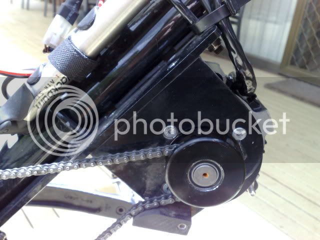
recumpence said:The chain pulling torque will make the drive want to rotate toward (in your case) the crank. I have no worries, though, because Jozzer will know how best to mount and brace it.
Matt
deecanio said:you could well be right bud, was just an initial thought on mounting, do you have a piccy of how the 1000w motor was set up so i can see what forces were involved?
i'm not sure at all how this will pan out but looing at the wonder drive it seems to me that we have on one side the motor pulley and big pulley and then on the other we have the drive sprocket and the crank sprocket, naively i thought that hopefully these two forces might somewhat balance themselves out? looking at matts drive and with it mounted to the seatpost which way would you think the drive will rotate? it's a tricky one i know but any thoughts?
Cheers,
D
Gary said:I think that "for the masses", a frametube mount will be the preferred solution, as most just won't have access to welders and/or fab shops for doing a custom mount. I predict most of your future sales will be with this option.To start the ball rolling, I would be happy to pay you whatever you need to do a prototype. The spec is simple, just do one that will fit on a standard size, round frametube (1-1/4"?) and that centers the assembly on centerline of the frame. As I envision it, this mount would be two-pieces, one that has half the clamp, plus the part needed to go over the bearing tube, and then the other that is simply the other half of the clamp. I'm sure, however, that you can figure out what would work best, and/or is the easiest to make. It could even be 3-pieces, with one that is your existing mount, and then have the clamp mount bolt to it. The tube mount could simply be an add-on option. Whatever works.
recumpence said:I am open to anything. I do not mind prototyping. That is part of the whole production gig.
Matt
 i wasn't expecting it to arrive that quickly, did you get my motor yet too? oh man, it's all coming together