• Hello ES! We could use some help to get us past the finish line on building the new knowledgebase for the forum.
    Can you donate? Please see our fundraising page. Thank you!

How to properly integrate front and rear blinkers on a 72v system?!?!

6DiaBLo6BLanCo6

New here
Joined
Feb 19, 2026
Messages
2
Location
Melbourne Florida
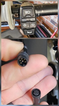
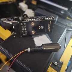
Good evening to all... I first would like to thank in advance anybody that's willing to give me some tips and words of advice, im relatively new to the E-bike world and this is my first ever "Social Community Post" on the subject.. So i would really appreciate the knowledge from the individuals in this thread, and look forward to getting some help (before I make a mistake and just Fry everything) lol... I recently bought the Happyrun "Tank" G300 Pro Ebike 72v, 30Ah battery on a 3000w/6500w peak rear Hub motor and 50w generic "made in China" controller. And the Stock electrical system is setup using Julet 2,3,4,5, and 6 pin connectors... I wasnt looking for a hotrod E-moto, but wanted something for everyday commuting that wouldn't have 5-0 pulling me over constantly. After 4 months ive had no issues with the cops, or had any issues with the bike itself.. The only blinkers on the bike are the ones that are integrated into the back taillight and cant be seen by anyone other than the cars behind me, so what i want to do is to add blinkers to the front and rear of the bike. I bought 2 sets of blinkers off Amazon that are 3 wires each and state that they are for a 12v system, hooked them up and they all worked well when tested with a 12v ac/dc wall adapter... but when I spliced into the 6 wire rear brakelight cable adding the 2 red and 2 black blinker wires to the existing red and black power and ground i get power to the rear brake light and integrated blinkers but no power to either of the new blinkers, even after connecting the 3rd signal wires of the blinkers i still get nothing. So before I go and mess something up I figured it best to get some answers on what im doing wrong, im attaching several photos that I hope will help to get me the answers that im looking for. 1000004466.jpg1000004407.jpg
 
first have you confirmed that the 4x buttons on the handlebar unit and a brake cut off are all present in the 6 pin plug displayed And have you identified which pin is what?

How did the 3 wire blinkers work? did grounding the signal wire start them flashing when supplied with 12v? or?

where are you getting 12v from on a 72v ebike if controller supplied BE AWARE of any current draw limits your blinkers may exceed. a discrete 12v regulator for aftermarket lighting additions is a good idea to avoid unforseen side effects of overloading a limited 'low' voltage supply.
 
first have you confirmed that the 4x buttons on the handlebar unit and a brake cut off are all present in the 6 pin plug displayed And have you identified which pin is what?

How did the 3 wire blinkers work? did grounding the signal wire start them flashing when supplied with 12v? or?

where are you getting 12v from on a 72v ebike if controller supplied BE AWARE of any current draw limits your blinkers may exceed. a discrete 12v regulator for aftermarket lighting additions is a good idea to avoid unforseen side effects of overloading a limited 'low' voltage supply.
Okay for starters when I first hooked the blinkers up I used a 12 volt AC DC wall converter so I never had them hooked up to the bike and running, as for the finding out which pins are for what I did not do it with a multimeter but found on several different sites where they stated that the wires were for ground (black), main power (red), left blinker(blue), right blinker (yellow), tail light running(orange), and taillight brake light(brown). On the controller itself it has a 12-pin connector that connects separate to the main 3 leads for the motor or the red and black wire that connects to the actual battery itself, I even noticed that there were several extra wires that did not run anywhere off of that 12-pin connector. But when checked with the multimeter I wasn't getting more than 6 volts coming through... But when I take the blinkers back off of the circuit, and rewire everything up it works perfectly fine.. can you give me an example of a 12 volt regulator that you're talking about and how I would set that up because I'll totally do it. I appreciate your time for commenting
 
Full Disclosure-- search my post history as my #1 big ebike mod idea is very similar to yours.. ( it was lights that were primary indicators secondary..) Though my project is still in the -to-finish box.. (times i have cycled i the dak in the last few years - once? twice?)
So I have some insight but no proven solution route..

google for "DC-DC Step-Down Buck Converter" Bung an 'Automotve' or 'ebike' in te search string perhaps?
But buy this last after all lamps etc so you can asess the max currnet in amps you will draw ad can buy a suitable device.

You can buy flasher units to pulse the indicator signal ala 20th century tech. But i sourced cheap ali express 2 wire m/cycle led 'waterfall' indicators that simply pulse in unison as long as they get power at the same time.. (no flasher unit needed).

Keyboard battery issues atm .. I will continue later when resolved..
 
Last edited:
wired keyboard unburied..

You cant assume on is the same as +voltage on the relevant signal wire. often, as with the ebike brake cut off sensors pulling down to ground to register 0v is the activate signal.. so verifying the wire outputs relative to switch positions is fundamental.

(If just carrying a logic level voltage of ? 5v? you can source a single relay module for hobby use on a pcb with screw terminals to use the logic level voltage to switch the regulated to 12v battery power as needed..)

I used a pen and paper to sketch out and plan my hi amp lighting and indicators circuitry but tools exist for digital versions if you prefer. If you have any doubts after doing so post the plan for review..
 
Last edited:
Back
Top