How To tune up the PWM frequency

Keep in mind, as you go higher in voltage, that sometimes a brushed motor (especially with long wires to the motor and battery from the controller), generates lots of RF voltage spikes, some of them really high. If any of those are high enough, they could pop MOSFETs. It might even be possible under the right conditions to generate a *negative* spike that is negative enough voltage to trash a FET in a different way.

Current spikes thru a motor generate voltage spikes, too. Bigger current spikes mean bigger voltage spikes. I don't expect that's as big a problem as the RF from the brush arcs, but it does get worse the higher in voltage and power you go.

I don't have a link to the data, but 4QD in the UK has (or had) a page with data and observations about brushed motor controller failures.
 
Just handling the FETs can blow them with static electricity. Could have been defective too.
Good you got it running.

I recall others in the past destroying the gears in those units with increased power. The chain drive is much more robust. Currie made both types at one point or another. You may be able to at least find the rear sprocket and hub parts off the shelf. The motor itself has a very good track record. At 48v and lots of current, you can easily pull a wheelie. At higher voltages, it would be good to reduce the current limit, but there's no adjustment for that. A long time ago I made a current limiter circuit for one of those that would tie in to the throttle line to keep the amps from going over a set point. It actually worked quite well.
 
Well, it crapped out big time. I just put everything back together using 5 batteries instead of my usual 6. I lightly applied the throttle and the wheel started to turn a tiny bit with that usual whine and then the magic smoke was released so I guess the controller blew again. I only applied maybe 5-10% of throttle for about 2-3 seconds and even the wires between the batteries got hot. I am kind of baffled as to why. I can accept that the controller needs to be replaced but I now wonder if the motor was just at a sweet spot when I ran it with 24volts. The thing is my test loads that I used on the bench were a cordless drill that measured 0.8 ohms and a fog light that measured about the same, maybe 1 ohm. So this motor with an impedance of about 1-1.5 ohms doesn't seem that bad comparatively. I could find no reference of any kind of what normal resistance readings of this or any similar motor would be. But when I connect it directly to any battery it starts off fast and seems to sound and run like it always has with no high amp draw heating wires up. Part of me is thinking that the different MOSFETS and or Schottky barrier diodes are not working as well with this controller. At least not well with my setup. Maybe something else is wrong. I am not sure what to do. If I buy another YK43 controller then I will be back where I started.... with a short life span to be where I want to be (32mph). I can get the Currie rear wheel that has the chain gear on it and it will fit perfect and I can then run at 48 or 60 volts and last much longer I am sure since this controller was sold as a 60v controller. But I will probably lose rear disk brake unless I can fit the disk onto that wheel somehow and I will then have to buy a chain, motor sprocket, and weld to this motor after grinding down the helical gear, etc.. I guess the only way to see if the motor is not drawing too many amps before buying another controller is to launch with 48v or so hooked up directly to the motor via on off switch and hang on for 10 minutes to see if the wires are melting away. :roll:
 
Hmm... with brushed motors and controllers, the current is higher at partial throttle than full, IIRC (assuming a good load on there). So that could explain the heating of the wires.

But I assume you were doing these tests with wheel offground, unloaded?
 
You can test the motor by running it with the wheel off the ground. What you really need is a way to measure the current when doing this. Do you have a CA or big shunt you can use to measure the current? The amp mode on most voltmeters is not going to have enough capacity and will likely destroy the meter.
 
I was running wheel off the ground. I don't have anything better than a couple usual DMM's but I just thought of two things. 1) I have a customized golf cart with an ammeter. I can take the shunt from my golf cart and hook it to the scooter with extended wires going back to the golf cart gauge. 2) I think I may still have the old controller somewhere in my garage. I moved some stuff around recently but if I can find it I can just hook that one back up at 36volts and see what happens. I really don't think the motor is going to be bad.
 
I know it's a dead horse by now but incase anyone is curious....

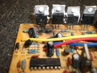
I found and reconnected the old controller with 36v (it's a 36v controller) and it ran perfect with the motor no heat or anything bad. I only tested it for a few minutes but I did a lot of the running at low throttle where it seems to strain the most. The YK43 controller literally smoked and everything got real hot after just 1-2 seconds. I am starting to think that the new MOSFET's need a different bias resistor or something. I removed the YK43 board again and on 1 side it seems to have saved itself by melting the solder off of the middle leg of the barrier diode. On the other side it got weird, it vaporized one of the MOSFET's but all the others seem totally fine. I also noticed that the big 470uF 100v Capacitor on that side now has a bulge at the top of the cap where the other is normal, flat or slightly depressed. So in the least I will need 1 resistor, 1 cap and another MOSFET to "fix" the board and I have one last spare MOSFET BUT, something else is going on here. Maybe the MOSFETS need different bias resistors or something. The load (the motor) is obviously fine since the stock controller ran it fine without even getting room temp. So the controller is roasting itself at the first sign of load. I am planning to buy another YK43 and start over since they are cheap BUT it is obvious that stock they won't last too long for me. So I want to do the upgrades of better MOSFET's and Schottky barrier diodes but my guess is that a brand new YK43 with these parts will fry instantly. Photos of damaged board attached. Capacitor bulged on the side with bad MOSFET, all but one resistor is fine. Ones parallel to transistor terminals are all ~6.8k, ones perpendicular are all ~980 ohms except one by bad mosfet that now reads ~750 ohms due to the nuclear roasting nearby.

{Fetcher} Did you have to change any other parts when going with the IRFB4110 MOSFET's?

EDIT: Maybe THIS is my problem. FAKE 4110's I stumbled on this thread while searching for the IRFB4110 datasheet. http://endless-sphere.com/forums/viewtopic.php?f=2&t=10655


008.jpg
 

Attachments

  • 006.jpg
    006.jpg
    72.8 KB · Views: 1,072
  • 005.jpg
    005.jpg
    86.6 KB · Views: 1,072
If a cap is bulging, it could be voltage or heat killing it, or simply defective in the first place.

But if it is bulging, it also means it's not absorbing the voltage spikes (mostly from brush arcing) that could kill FETs.
 
I agree but I am real sure that before the latest burnout, the cap was not bulging at all. I noticed it right away this time. The cap that has the bulge is on the side that blew a mosfet this time but one on the other side was bad last time. Also the other side is the side that melted the solder off the barrier diode. I am not sure what is causing it but every time this controller tries to operate with the new mosfets it is like it is running 200 amps or something. It catches fire almost instantly. I am going to try and find a better controller but am baffled why this one won't hold up now.
 
After having a nights sleep on it, I am sure that I got counterfeit IRFB4110 MOSFET's. I got them from e-Bay from a China seller who sold 10 at a time for $10.00 shipped. Now that I look at even the 100 unit cost from trusted suppliers like Mouser, Digikey, Jameco I realize that the price was probably too good to be true. Plus mine look like the ones described as fakes in the thread about counterfeit 4110 MOSFETS. This makes the most sense. I only needed 8 for my YC43 but out of the 10 I ordered 1 failed the instant power was applied even at my testing voltage of 36v with the wheel off the ground. Then after replacing that one I was able to bench test with a low test load of a light and cordless drill at 24 volts and it did "work", but once again the second I connected 60v and the scooter motor it didn't make 1 rotation and smoked again. I think these are low grade and fail the instant you actually try to even get into any power at all. I noticed that the gate diodes I bought from DigiKey are just fine and melt the solder but show no signs of overheating or failure.

I am taking a wasteful 2 pronged approach. I ordered a YK43 controller that looks a lot different from my YC43. I will install that right now to get running. Family is coming in for thanksgiving they want to ride the 32mph scooter that does wheelies. I am also going to go ahead and replace the MOSFET's and replace/upgrade the two 100v 470uF caps in the YC43 controller. I think the YC43 is a bad ass controller that I just pushed too far since the MOSFETS it came with were only rated for 75v max and a fully charged 72v pack hits 80v easy. I never believe in pushing anything past 80% capacity and I had been running mine at 100% for about 2 months riding a few times a week with never less than a 190lb rider and a way oversized wheel diameter demanding even more startup torque. If I am right I will have another YK43 to use in ~2 days (love Amazon) and I will soon properly fix the YC43 I already have.

I guess I really am geek. I can afford to buy a huge Kelly controller if I wanted to, and still prefer to waste time fixing this stuff that = WAY more than I earn working. :?
 
Back
Top