Hubmonster teardown

eee291 said:
You have to multiply battery Current x Volts to get your power (Kw) not phase Current.

Depends on what you are saying. Phase amps can be and is commonly much higher than battery amps. If they were the same no one would make the distinction between battery and phase amps.

battery watts = battery amps x battery volts
motor watts = phase amps x battery volts
 
fubgumfaw said:
eee291 said:
You have to multiply battery Current x Volts to get your power (Kw) not phase Current.

Depends on what you are saying. Phase amps can be and is commonly much higher than battery amps. If they were the same no one would make the distinction between battery and phase amps.

battery watts = battery amps x battery volts
motor watts = phase amps x battery volts

This is incorrect. Motor watts should be phase amps * motor voltage. Motor voltage is not something we typically have easy access to.

Phase amps can be higher than battery amps. Using your calculations, motor power would be higher than the power provided by the battery - clearly impossible.
 
Depends on what you are saying. Phase amps can be and is commonly much higher than battery amps. If they were the same no one would make the distinction between battery and phase amps.

battery watts = battery amps x battery volts
motor watts = phase amps x battery volts
agreed, this is incorrect. you'd be into free energy if this was true :mrgreen:

battery watts = battery amps x battery volts
motor watts = phase amps x phase volts (this is simplified, i'd guess you have to take into account a power factor here)

if phase amps are higher, then phase volt needs to be lower, otherwise more energy out than in.
 
fubgumfaw said:
Lets call these what they are...6 phase hub motors. No idea what a "hubmonster" is! That's totally non-descriptive.

I have one with the attached cast 10" rim and that's got a 60mm tall stator in it.
I have 2 with the bolt flange and they have 65mm tall stators in them.
I have 2 more of the 65mm version on scooters I have yet to mess with.

In testing motor power, I cooked the halls in one of my 65mm, 6 phase hub motors. I'll need to replace them after a while...oops!

I have a Zap scooter which has this one in it. I machined vents in the covers. It is running on 2 Nucular 24 fet controllers at 82v. I see peaks of 309 phase amps according to the controllers. That's 309 phase amps PER CONTROLLER or 25kw per controller. Most of the time, I see more like 200 phase amps or around 16kw per controller. My top speed, before I took things back apart to add more battery power and a few other things was 75mph at 82v. No idea what I'll get once I put it back together! I might have to find a couple of FOC controllers capable of 150v and see what happens there. They are pretty capable motors! If you hunt around you can find them on scooters for pretty cheap. That's how I found all of them I have. I never paid more than $450 for a complete scooter that included the motor. Craigslist is your friend! You might get lucky and find one right away or it might take a while...can't really say. In my area, I check Craigslist pretty regularly and they crop up from time to time.

https://imgur.com/Aaa6pJy
https://imgur.com/buWMudV
https://imgur.com/tedvKHg

The drop outs and torque arms were not made to hold peaks of 50kw. I had to machine much beefier torque arms from 1/4" thick steel. These new arms are still on there now, but I need to make a better set that clamps around the motor shaft flats. They are already showing signs of wallowing out like the drop outs!

https://imgur.com/RZYCB2J
https://imgur.com/anY5scQ
https://imgur.com/zjwjtJD
https://imgur.com/Lu7vV6e

nice work with the cover vents!
im super interested in your build performance cause i was going to go with a similar combo with the 24fet nuculars. funny, you needed more battery! wonder why... :D i was going to start with 22s20pvtc5A.
will say this- as you say, you will need way better torque arms than the ones you made, and the stupid washer thing that came with the motor...i would have just binned that from get go.

thats serious power and id say you need min 20mm tensile steel plate with a design that pinches up with a 8 or 10mm tensile bolt.
yep, thats not from my engineering calculations, thats just instinct from school of hard nocks.
 
I tryed to find a link but can not find the motor again i seen a qs motor branded as ym motor red and black with rsm air vents on the side it had 6 16mm cables coming out making up the phases and liquid cooling it was a 12 inch moped hub proper nice looking price was a grand not even shipped.

I come across it looking at taiwan electric mopeds and this was eating 50kw no issues he could hardly get on it because it was pure evil he was small and the frame positioning of a moped was showing its limits.

Ill try and find the link but im all over the place and never bookmark so needle in haystack.
 
would be great to have a look at that. the thing with the hubmonsters as i understand is the quality of the materials in the motor, big fat motors are not so hard to find but they may not have the efficiency.
 
Voltron said:
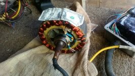
KIMG0192-800x450.JPG

No idea how wide a $1 bill is, but the stator is 65mm wide.

For all the egg heads out there NOT making explanations, just saying I"m wrong, feel free to post real math or white papers or whatever. What I can tell you is the dual Nucular controllers are reporting peaks of 309 phase amps and I see 250 battery amps PER controller. There is nothing in a controller to regulate voltage downwards. All that happens is mosfets turn on and off in a specific pattern that creates a more or less sinusoidal current wave form in the motor. IF in there you can "somehow" create a way to lower battery voltage, feel free to explain how. About all I see that is possible is the small voltage drop across the mosfets, phase wires and motor phases. Phase amps being routinely higher than battery amps is something I've come to expect. This is far from the first time I've seen it or the first time that others have reported on it. No one is saying "magical energy" and I don't know why it's this way, just that it is.
 
ridethelightning said:
nice work with the cover vents!
im super interested in your build performance cause i was going to go with a similar combo with the 24fet nuculars. funny, you needed more battery! wonder why... :D i was going to start with 22s20pvtc5A.
will say this- as you say, you will need way better torque arms than the ones you made, and the stupid washer thing that came with the motor...i would have just binned that from get go.

thats serious power and id say you need min 20mm tensile steel plate with a design that pinches up with a 8 or 10mm tensile bolt.
yep, thats not from my engineering calculations, thats just instinct from school of hard nocks.

Field weakening works really well with this motor. I think the motor is 16Kv and at 82v that's 1312 RPM. On the 10" tires, I was flat out at about 62 or 63 mph without FW. With FW on the 10" tires got me 75 mph before I chickened out. I frankly did NOT want to push those light weight scooter tires faster and then have issues. New 12" tires and wheels on there now.

Geez! Torque arms...LOL...I had little expectation the factory ones would last very long, but I did think they would last longer than they did. I think I got 30 miles out of them before they were completely useless. The ones on there now are 1/4" 4041. They are holding up OKish, but there's not enough surface area outside the drop outs for them to be long term. I'll make clamping ones that have a flange to go inside the dropouts and pick up the rest of the motor shaft flats. Even then...the amount of torque on those flats is crazy!

I was not having issues with over heating once I ventilated the motor. It did just great staying sufficiently cool. It has 2 PTC temp sensors in it now and each Nuc controller has the motor temp cut off set so that I don't cook the motor.

The EV thread:
https://endless-sphere.com/forums/viewtopic.php?f=10&t=108350&p=1654837#p1654837
 
There is nothing in a controller to regulate voltage downwards

There is. If you don’t know then please be a bit more humble (or you could end up like the original poster of this thread, he was throwing tantrums enough to get kicked out just because he was wrong and couldn’t accept it.)

It’s called PWM, used in every switching power supply to go from a higher voltage to a lower.

Breaking the rule of energy conservation indicates that something is wrong, no matter what your display says. In this case it gives the clue that the voltage of the phase amps needs to be lower than battery voltage.
 
larsb said:
There is nothing in a controller to regulate voltage downwards

There is. If you don’t know then please be a bit more humble (or you could end up like the original poster of this thread, he was throwing tantrums enough to get kicked out just because he was wrong and couldn’t accept it.)

It’s called PWM, used in every switching power supply to go from a higher voltage to a lower.

Breaking the rule of energy conservation indicates that something is wrong, no matter what your display says. In this case it gives the clue that the voltage of the phase amps needs to be lower than battery voltage.

I have to tell you that PWM is on/off pulses, NOT voltage regulation or step up or step down. Are you claiming that the motor is acting as the inductor in a DC-DC converter WHILE it is operating as a motor? Still NOT seeing any form of DC voltage reduction in circuit in a controller or motor while they are operating. Feel free to actually explain in real terms instead of saying "you are wrong". Also, I'm not an idiot...USE LESS condescending language!
 
You might want to read up on controller function.
It was just a google away for those that wanted to learn:
https://www.digikey.at/de/articles/why-and-how-to-sinusoidally-control-three-phase-brushless-dc-motors

This is just an example, plenty of different control techniques out there.
 
fubgumfaw said:
larsb said:
There is nothing in a controller to regulate voltage downwards

There is. If you don’t know then please be a bit more humble (or you could end up like the original poster of this thread, he was throwing tantrums enough to get kicked out just because he was wrong and couldn’t accept it.)

It’s called PWM, used in every switching power supply to go from a higher voltage to a lower.

Breaking the rule of energy conservation indicates that something is wrong, no matter what your display says. In this case it gives the clue that the voltage of the phase amps needs to be lower than battery voltage.

I have to tell you that PWM is on/off pulses, NOT voltage regulation or step up or step down. Are you claiming that the motor is acting as the inductor in a DC-DC converter WHILE it is operating as a motor? Still NOT seeing any form of DC voltage reduction in circuit in a controller or motor while they are operating. Feel free to actually explain in real terms instead of saying "you are wrong". Also, I'm not an idiot...USE LESS condescending language!

Average voltage over time is lower though, the motor/controller isn't creating energy
 
I see it as the 3 phases ac combined signal equal the dc input plus fet losses etc.

There maybe peak phase currents higher than the input current but with ramping time so the total power of each phase pulse combined would equal the dc input.

So a 300amp controller can have 700phase amp peaks but the 300amp is constant but the 700amp is not, so if both sides were ploted on a graph the total area of power under each side would always equal out.

Pwm can control voltage with pulses its like nudging and depending the duty cycle the percentsge of the source voltage gets through its how some brushed dc controllers work H Bridge setup forward backwards plus throttle control with 4 fets then theres half bridge thats just throttle control.
 
Voltron said:
KIMG0192-800x450.JPG

classic pic. it looks like the outer shaft has seen some corrosive forces, but looks like the inside is still clean as a whistle, these motors have a rep for being well waterproofed.
 
Ianhill said:
I see it as the 3 phases ac combined signal equal the dc input plus fet losses etc.

There maybe peak phase currents higher than the input current but with ramping time so the total power of each phase pulse combined would equal the dc input.

So a 300amp controller can have 700phase amp peaks but the 300amp is constant but the 700amp is not, so if both sides were ploted on a graph the total area of power under each side would always equal out.

Pwm can control voltage with pulses its like nudging and depending the duty cycle the percentsge of the source voltage gets through its how some brushed dc controllers work H Bridge setup forward backwards plus throttle control with 4 fets then theres half bridge thats just throttle control.

This is what LARSB didn't do. He clearly needs to be worshipped and to sit on his pedestal of ego. Too bad for LARSB! I mean really...how hard is it to just say what was was said here by Ian instead of "your wrong"? One presents practical information and the other presents ego and a need to worshipped. Just my point of view...I'd rather have the practical info! Maybe LARSB is a rocket scientist and can't be bothered with lowly plebs like me?

So Ian...I appreciate the explanation and yeah...totally makes sense! I never said that the motor was seeing 309 phase amps continuous, just that the controllers were reporting peaks of 309 phase amps. Your explanation fits this fact. It also fits the facts that I have observed previously with other motors and controllers where I'd see phase amps far higher than I'd see battery amps. I was not checking motor voltage, but my assumption was what I have described previously...aka battery voltage minus some small losses was in the motor so that the motor sees basically battery voltage. PWM doesn't change this, just changes how long there is battery voltage or zero volts. From the perspective of time and averages...I suppose it is right to say that the average is lower voltage, but when on, the motor see battery voltage and when off, it sees 0v. This is why PWM works so well in preserving motor torque for brushed tools. The motor is seeing either full voltage or no voltage...alternating very quickly.
 
ridethelightning said:
Voltron said:
KIMG0192-800x450.JPG

classic pic. it looks like the outer shaft has seen some corrosive forces, but looks like the inside is still clean as a whistle, these motors have a rep for being well waterproofed.

One of mine sat outside for who knows how long. I bought the scooter for stupid cheap! The motor shafts were covered in rust. Inside the shell was minty fresh...like the motor had been built last week. That was due to the shell being sealed up with silicon and the axel using seals on both sides. OF course, my motor is all opened up...LOL...never going to stay minty fresh like that!
 
yeah i was tempted not to open mine just to keep the original seal, but ill probably do it some time just from curiosity. guese i can always seal it back up too.

i think ill try dual max e to start off as i have a few kicking about... :|
id love the nuc 24s but thats serious doe, and more controllers in my hoard.
 
fubgumfaw said:
This is what LARSB didn't do. He clearly needs to be worshipped and to sit on his pedestal of ego. Too bad for LARSB! I mean really...how hard is it to just say what was was said here by Ian instead of "your wrong"? One presents practical information and the other presents ego and a need to worshipped. Just my point of view...I'd rather have the practical info! Maybe LARSB is a rocket scientist and can't be bothered with lowly plebs like me?

No, not really needing worship or ego. I pointed out an obvious mistake. It is not my responsibility to lead you onwards from there. You already sound a whole lot like your predecessor Electricgod.
Couldn’t stay away, could you?
 
yeah i was tempted not to open mine just to keep the original seal, but ill probably do it some time just from curiosity. guese i can always seal it back up too.

i think ill try dual max e to start off as i have a few kicking about... :|
id love the nuc 24s but thats serious doe, and more controllers in my hoard.
 
ridethelightning said:
yeah i was tempted not to open mine just to keep the original seal, but ill probably do it some time just from curiosity. guese i can always seal it back up too.

i think ill try dual max e to start off as i have a few kicking about... :|
id love the nuc 24s but thats serious doe, and more controllers in my hoard.

If you have a few max e.. that’s a lot of ebike dollars :D
 
ridethelightning said:
yeah i was tempted not to open mine just to keep the original seal, but ill probably do it some time just from curiosity. guese i can always seal it back up too.

i think ill try dual max e to start off as i have a few kicking about... :|
id love the nuc 24s but thats serious doe, and more controllers in my hoard.

I've never messed with Adapto products. Can Adapto controllers "talk" to each other like Nucular controllers can? AKA CANBUS or some other method? Its not super important really. The original dual 12 fet controllers that came with these motors were simply 2 controllers inside the same shell. They shared the same throttle signal and if the low/high speed option was used, that too. Otherwise...they were just 2 very basic controllers in the same box. Since you have programmable controllers, It's probably best to do all your motor setup one half at a time and turn off the other controller so it doesn't interfere in any way. These motors are simply 2 sets of halls and phases wound onto the same stator. You can run either half of the motor 100% independent of the other.

The biggest challenge, and it's pretty small is getting the hall/phase combination correct. Looking at the stator and halls, you can't see which set of halls goes with which set of phases. These motors commonly came with a white connector with both sets of halls in the connector. It's pretty obvious that you have 2 rows of 5 pins and that's a set of halls. Worst case scenario is you have a 50/50 chance of randomly selecting the wrong set of halls for the phases. It's just my opinion, but the bodged on hall connector is not ideal. Also, once I figured out which set of phases goes with a set of halls, I'd like that preserved forever. As a result, I cut off the hall wires at the bodged on connector. I then used individual connectors for each set of halls. Once I discovered the right set of phases for a set of halls, they got bundled together. I also removed the ring terminals and replaced them with 6mm bullets. This all made it easy to connect or disconnect half the motor easily without effecting the other half.

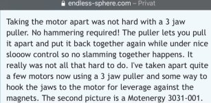
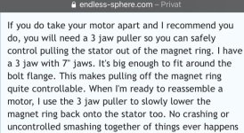
If you do take your motor apart and I recommend you do, you will need a 3 jaw puller so you can safely control pulling the stator out of the magnet ring. I have a 3 jaw with 7" jaws. It's big enough to fit around the bolt flange. This makes pulling off the magnet ring quite controllable. When I'm ready to reassemble a motor, I use the 3 jaw puller to slowly lower the magnet ring back onto the stator too. No crashing or uncontrolled smashing together of things ever happens that way. Curiosity is a good enough reason to take it apart IMHO. Even though there are lots of good pics of these motors out there, I'd still take it apart just to look for myself. Sealing it back up is easy. It's just silicon caulk in the side cover joint. OF course, if you want to use yours like I use mine, well you will want to open up the sides somehow.

Elongated slots like I milled out are not that critical. You could get by with evenly spaced drilled out holes in the side covers. This is less effective than long slots, but any airflow into the motor is a good thing. If you wanted to get wild, a DELL server fan blowing in the general direction of the opened up side plate holes will create a lot of internal air flow to keep the motor cool. They are pretty loud, but they move a lot of air for their small size. You will have no problem finding them on ebay for super cheap!

https://www.ebay.com/itm/124528407359?_trkparms=aid%3D1110006%26algo%3DHOMESPLICE.SIM%26ao%3D1%26asc%3D232196%26meid%3Ddbc3e017635e4dee8ac8ac21b5902a8f%26pid%3D101195%26rk%3D2%26rkt%3D12%26mehot%3Dlo%26sd%3D353338082713%26itm%3D124528407359%26pmt%3D1%26noa%3D0%26pg%3D2047675%26algv%3DSimplAMLv9PairwiseUnbiasedWeb%26brand%3DDelta&_trksid=p2047675.c101195.m1851
 
Back
Top