INFINEON CONTROLLERS FOR DUMMIES

how much current can the infineon controller deliver on its 5v supply? Can the onboard dc-dc put out a lot or not? I am wondering if i used it to power devices on the bike if it would be a problem.

I added a power line out of the controller here for future:
 

Attachments

  • CA_Connections 2.jpg
    CA_Connections 2.jpg
    104.3 KB · Views: 3,600
Can the infineon be powered up with any sla 48v charger directly for flashing or should the phases, halls, throttle be hooked up first etc.
I wanted to power it up to flash it. I am getting antsy without a battery....

48v charger can be used on it for normal testing and operation when i need to figure out which phase combination works? or should I just wait on the battery?
 
jeremy said you have to flash it while the power is off. you have no need to flash the LVC since you are using a battery pack with a built in BMS. the only need to adjust the LVC is if you are using SLA or nicads. otherwise you are good to go at 48V.

you really should not try to take power off the 5V supply. your regulators are not set up to deliver much current. if you need a current source, try using a dc converter off the pack, it is more efficient anyway and you won't burn up your controller trying to get current on the cheap.

the entire voltage drop would just be heat anyway if you used the 5V supply, so if you are gonna drive leds then just string them in series with your battery pack for cheap and add enuff restance to keep the current through the leds in spec. that is cheapest, and least amount of wasted energy as heat.
 
I want to change more than the LVC.

OK so it is flashed without battery source and the computer powers the controller for flash. That is what I thought but I cannot get the computer to detect it. I am concerned that the usb-ttl i bought is defective. Does not even show change in device manager when attached. no computer beep or anything when plugged/unplugged.

Is the ttl-usb defective or maybe something else?
 
I figured out the USB problem myself. Many of the USB-TTl chips come set up for an external power supply and will not work unless you jumper them to run off of the USB power as is our case.

For mine I had to jumper these 2 points and all was well.
 

Attachments

  • 002 copy.jpg
    002 copy.jpg
    65 KB · Views: 8,163
Having same problem aswell I will try jumpering. although my bafang seems to be coping on 66.6v with no current limit set on the controller, makes it quite a fun ride. :twisted:
 
OK Gurus!

More questions. I have almost finished my throttle interrupt circuit (it works) but I would like to have the throttle cut out slightly before the realys switch from delta/wye as this allow the phase lines to come to 'rest' so there is no load for sure. my question is how long from when throttle cut off will this take? if it is instant then great. I was planning on having about 10ms. Will this allow the controller to come to rest in time?

fechter made this comment:
caleb7777 wrote:If the +5v to throttle is interrupted, it will send a throttle output of 0 yes? or no?


Yes. Interrupting the 5v to the throttle will do about the same thing as pulling down on the throttle line, but with less chance of frying the throttle.


Which route is safer? (and fast, we are talking ms) I can easily cut the 5v+ to throttle because of where this circuit will be but I could also do the pull down method if I must

If I should how do I implement it?
 
Since this is the dummy's thread I better make my appearance.

Can someone point me in the direction of some easier to follow directions for installing the usb module into the infineons. I am having a hard time finding what I need to do it safely/don't want to lose a good infineon to dummying.

thanks
 
Simply wire it in as per this diagram with a switch on the power line (vcc).

Infineon cheat sheet.jpg

The USb adapters often come with a 'usb power' jumper that will ned to soldered across in order for power to come from the computer.
ie: the one in the pic normally only has the ground, rxd, and txd pins going to comp. By jumpering the "USB power" it allows the vcc to the 5v of the computer and powers your device so you can flash.


file.php


The controller doesn't have nice white pinout in the pic, just 5 solder points, the middle one is left alone

Here you see mine. Green with black stripe goes to RXD on the adapter


DSC00090-2.jpg

And the USB side of it:
DSC00093.JPG
 
caleb7777 said:
Simply wire it in as per this diagram with a switch on the power line (vcc).

Nice :wink:

-methods
 
someone might want to comment on this, see if i'm on the right track:
for 12fet xie cheng
if using a separate power source for the low voltage circuit ( in my case 28v approx), and a different power source for the mosfets ( approx. 86v), then I'm guessing regen braking voltage will not be limited by controller, as it is connected to the low voltage supply for detecting voltage???
part 2: not related to above scenario: just using one power source for controller:did some figures on what value to use to get about 95v max regen voltage would need to put 2058ohmn ( approx 2k) resistor in parallel with r12
using 42v as lvc with software would give about 67v as new lvc and 95v as max regen voltage
anyone want to verify my maths??
 
solarbbq2003 said:
someone might want to comment on this, see if i'm on the right track:
for 12fet xie cheng
if using a separate power source for the low voltage circuit ( in my case 28v approx), and a different power source for the mosfets ( approx. 86v), then I'm guessing regen braking voltage will not be limited by controller, as it is connected to the low voltage supply for detecting voltage???
That is correct.
In fact, using (3) 9V batteries is plenty to power the "ignition" circuit.
The max current draw is only about 65ma (regardless of 6,9,12,15, or 18 fet models AND/OR Infineon/116 MCU).
Realize that the ignition circuit and the mosfet POWER are completely independent circuits within the controller.
You will need to monitor your main battery independently to ensure against any LVC damage (of course).
And for 27V to work, bypass (or mod) all the power resistors and set the programmed LVC below 27V.
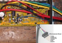
(Note: Some boards use the LM317 regulator and some use the LM393 comparator).

With this set up there will be no upper REGEN V limit.
AND the controller will run "Any Voltage" battery up to the MAX that mosfets/caps can take before exploding.

solarbbq2003 said:
part 2: not related to above scenario: just using one power source for controller:did some figures on what value to use to get about 95v max regen voltage would need to put 2058ohmn ( approx 2k) resistor in parallel with r12
using 42v as lvc with software would give about 67v as new lvc and 95v as max regen voltage
anyone want to verify my maths??

R12 (before mod) = 1200 ohm

Place a second resistor (2058 ohm) across R12

New value = 1 / (1/1200 +1/2058) = 758 ohm

The programmed LVC AND the programmed REGN MAX V are now actually increased by a factor of … 1200/758 = 1.58

A programmed LVC of 42V now is really 42 x 1.58 = 66.4

A regen Max of 60V is now 60 x 1.58 = 94.8
 
thanks for confirming mr K,
the battery i'll use for low voltage board is 24v 15ahr cobalt oxide lithium, approx 27-28v fully charged
 
Found this on arduino forum.
CA-42.jpg
C&P

I used a cheap ($3 on ebay delivered) Nokia CA-42 cable knockoff as a USB to serial adapter.
based on a Prolific PL2303 chipset which is supported under Windows and Linux.

Seems like a great way to get a cheap USB to 3.3V TTL...
If anyone is interested, I cut the end off of a CA-42 cable and discovered the following pinout:
yellow -> common
blue -> arduino TX
green -> arduino RX
red -> unknown

I downloaded the driver from Prolific's site. Version 1.0.2.5 worked for me in Vista x64. I was able to program my BBB freeduino and monitor returning serial data for debugging.

There are a couple disadvantages, the first being no 5V power to run the 'duino off of and second, you have to manually press the reset button. The second is actually a non-issue for myself as I don't like the auto-reset feature resetting my 'duino every time I start the Serial Monitor or plug in the USB cable or start the Arduino compiler. Then, there is the advantage of price, I paid just shy of $5 USD per cable shipped.

note: my cable runs at 0-3.3V on the TX line

Update: I found out that the usb end of my cable is not an injection molded plug, but with some prying I could pop it open. I then proceeded to solder the red wire to a +5V contact and behold, it now powers my Arduino too!! Now if only I could get the Arduino to bake me a cake....

Could this work to program the infineon ?
 
I dont know if that will work but I can tell you that the Infineon will program at 3.3V
I used a TTL to 3.3V RS232 a few months back.

-methods
 
hi
that looks like the prolific usb pclink that keywin is supplying now that uses a prolific chip i will post a few pics of the inside.

GEOFF
 
Hello,

I am new on this forum, thanks to all for the great work done on this controller, I have just purchased a new shenzhen controller blp3625 with XC846 to try to adapt it on my bike (golden motor kit 1kW with 48v battery 4Ah). I am also waiting for a usb - uart ttl converter bought on ebay to prog the controller.

I have a question about this controller I did not test it on my bike yet, when the battery level is going under lvc (with full throttle) what is doing the controller ?
- cutting power a few seconds to get voltage upper lvc
or
- limiting the power of the motor (smoothly) to be always upper the low voltage cut and without cutting the motor completely

I also found this information on a french forum :
after connecting the infineon X846 with hyperterminal (9600 bauds 8bits 1stop)

enter :
INP RS LOAD SIVO

the answer should be :
Infineon V3.42 software inc

then enter :
?

this would give you lots of parameters you can modify to be able to run sensorless for example or also give you information of voltage, courant... during cycling by rs232.

I really don't know if it works but maybe someone would be interested to try it. (I'll do it as soon as I can but I am a dummy for the moment)

Good day
Mitch
 
Takemehome said:
Found this on arduino forum.

C&P

I used a cheap ($3 on ebay delivered) Nokia CA-42 cable knockoff as a USB to serial adapter.
based on a Prolific PL2303 chipset which is supported under Windows and Linux.

Seems like a great way to get a cheap USB to 3.3V TTL...
If anyone is interested, I cut the end off of a CA-42 cable and discovered the following pinout:
yellow -> common
blue -> arduino TX
green -> arduino RX
red -> unknown

I downloaded the driver from Prolific's site. Version 1.0.2.5 worked for me in Vista x64. I was able to program my BBB freeduino and monitor returning serial data for debugging.

There are a couple disadvantages, the first being no 5V power to run the 'duino off of and second, you have to manually press the reset button. The second is actually a non-issue for myself as I don't like the auto-reset feature resetting my 'duino every time I start the Serial Monitor or plug in the USB cable or start the Arduino compiler. Then, there is the advantage of price, I paid just shy of $5 USD per cable shipped.

note: my cable runs at 0-3.3V on the TX line

Update: I found out that the usb end of my cable is not an injection molded plug, but with some prying I could pop it open. I then proceeded to solder the red wire to a +5V contact and behold, it now powers my Arduino too!! Now if only I could get the Arduino to bake me a cake....

Could this work to program the infineon ?

Well I bought one and it works. I programmed my controller.
RX TX GND are identified on the board, no guessing. Just solder a wire for +5v.

For those interested:

vendor: e_bestforyou
Item Title USB Data Cable for Nokia 3108 6108 6822 7250 7360 CA-42
eBay Item Quantity: 1
eBay Item Unit Value: $1.00 USD ( + $1.68 shipped to Montreal )
 
anyone have a com error pop up as soon as you hold to ground?? i cant seem to get mine flashed.


i can open software and adjust settings fine. i have a prolific driver installed. using the same usb cable everyone else seems to be using but as soon as transmit...then hold to ground ... i get com error 8020
8020 and program crashes.
perhaps im doing something wrong?

::edit:: program now works with driver http://lib.store.yahoo.net/lib/cooldrives/vista-prolific-chip-driver-for-serial-adapters.zip
 
I'm a doctor not an electronics tech, so help! I have a 6 mosfet 75n older Infineon that I need to set for a 30 volt cut off. It was being used for 48 volts. It has the little blue variable resistor on the back and it reads 388 ohms. Here are pictures of the large resistors and the variable one on the back that reads 388 ohms. What do I do to get 30 volt cut-off without destroying the controller. Thanks y'all electronic geniuses I did read the whole tech section Infineon stuff several times over, so you think I should be able to figure this out. Nope!
otherDocView attachment 1
 
The answer is so very simple.

1) No load test with bike upside down (or right side up but raised off the floor).

2) Controller hooked up BUT WITH COVER OFF.

3) A power source set at 30V (desired LVC voltage).

4) Run the motor (no-load) and turn the blue potentiometer screw until the motor shuts off.

You just reset the LVC to 30V.

PS ... When adjusting the POT screw ... don't short out the board with the little eyeglass screwdriver.

btw ... that power resistor looks a wee bit crispy. :shock:

docnjoj said:
I'm a doctor not an electronics tech ...
[youtube]bVhcB9ucmdg[/youtube]
 
Thanks Knuckles for the info and coming to the rescue again. dnmun, sorry to be a dunce, but is that the resistor with the gold, brown, red and blue bands? I read that at around 30 volts the power to the voltage regulator gets iffy and that can fry the fets? Is this a possibility? Yes Knuckles, thats where my opening line comes from! Bones is my hero!
otherDoc
 
Back
Top