
Hi
The transistor modification has gone through several stages of evolution, starting with a combination of an ideal controller that Knuckles wanted and a circuit design to achieve that by Fechter.

Original circuit diagram by Fechter
The Darlington transistor in this was found to be overkill so a revised design was done, made and tested by Knuckles using a 3055 transistor

This worked fine up to a point, it had one major drawback in red HEAT the transistor got hot, within working temperatures of the transistor. The temperature was above 60 degrees C once it was doing its job. The Infineon’s sent out with this modification worked but we still did not like the heat the transistor was giving off.
This caused Knuckles to brainstorm from shortly before Christmas and come up with a new circuit design that after a few revisions became the circuit below.

When it comes to making these modifications knuckles and I differ he has chosen the approach of joining the components together off the board and then mount them on the board.

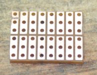
I decided to take the modular approach to this idea and make a small sub board that with legs that slot straight onto the main board where the power resistors go.

Geoff
The transistor modification has gone through several stages of evolution, starting with a combination of an ideal controller that Knuckles wanted and a circuit design to achieve that by Fechter.
Original circuit diagram by Fechter
The Darlington transistor in this was found to be overkill so a revised design was done, made and tested by Knuckles using a 3055 transistor
This worked fine up to a point, it had one major drawback in red HEAT the transistor got hot, within working temperatures of the transistor. The temperature was above 60 degrees C once it was doing its job. The Infineon’s sent out with this modification worked but we still did not like the heat the transistor was giving off.
This caused Knuckles to brainstorm from shortly before Christmas and come up with a new circuit design that after a few revisions became the circuit below.
When it comes to making these modifications knuckles and I differ he has chosen the approach of joining the components together off the board and then mount them on the board.
I decided to take the modular approach to this idea and make a small sub board that with legs that slot straight onto the main board where the power resistors go.
Geoff
")


