Instant Start 18 fet Infineon Boards are here...

Hi Guys
Some updates.
This is the 2nd issue of the schematic of the voltage regulator parts.
View attachment 4
This are the first results of my tests:
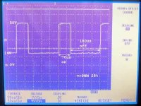
I have tested the controller at 50V and at 75V. The first screenshot is at 50V battery, no throttle and no hall-sensors connected, motor at no speed. Channel 1 is the voltage between Q2 and R1,R2,R3 to Gnd.
DSC03680_k.jpg
You can see the on and off switching of the switched series resistor. The on/off ratio is 28%.

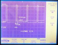
The second screenshot is at 75V battery. The screenshot is only showing 62V, because the oscilloscope input was overloaded. The on/off ratio is11% (no throttle. no hall-sensors, motor at no speed).If you add the throttle and no hall-sensors to 5V and the motor is running at full speed, the on/off ratio is up to 35%.
DSC03684_k.jpg
As you can see, the on/off ratio depends a lot on your 5V current consumption. Be careful, if you change the values of the resistors!!!

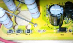
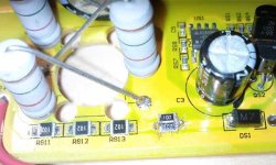
I guess, if you increase the base series resistors to 5K, you can use this voltage regulator up to 150V (the voltage limit of Q1 is 160V). I have you increase the base series resistors to 3.5K. These resistors I had in stock.
BTW: For voltages over 86V you need to lower R12. Otherwise you will have a overvoltage on the voltage measurement input of the uC. I have lowered R12 to 960R, which is good for input voltages till 107V.
DSC03639_k.jpgDSC03648_k.jpg
 
Sam-Pilot is a superhero and genius!

Thank you so much for your hard work!
 
Nice updates..!!

From now.. with the basic high current mod like i did ( no software program use).. just replacing the 3 serie resistor for a 3.0K 3Watts and replaced the 3 parallel 3W flameproof resistors for 3 x 2.4K,

I have absolutly no problem using up to 105V input and up tp 172A using 18 PURE IR 4110 mosfet on cooper bar heat sink.

no problem up to 105V !! :mrgreen: and... 172A.. !

max power obtained 15162Watts input.

i should receive the crystalyte 18 fets replacement controller that kenny promissed to me.. and i'll modify it by the same way.. but i'll use every of your new updates including USB cable and programming.

Doc
 
For some reason we always talk past eachother Geoff. :)
I just got done saying that method wont work.

Give it a try when your boards arrive.
If I am wrong, then great.

I found that even though I lifted the +5V (as described in that post) the chip was still powerering itself from the pull-up voltages of RX/TX.
This is why I chose to lift ground instead.

-methods


geoff57 said:
hi
follow the information in this post http://endless-sphere.com/forums/viewtopic.php?f=2&t=8610&p=164246#p164045 take note of linking the two pads to make the vcc output pad live at USB +5v methods you saw this post you posted just below, this is what most of the other threads do to program the controller.

Geoff
 
steveo said:
Methods why do you short that mini resistor on the right when adding the last resistor?

p.s. .. I haven't ever followed this new boards .. the last board i worked on similar to this was the original e-crazyman !! .. so bare with me !

-steveo

Nice work!

If you read back you will find that those three SMT resistors in series (1K 1K 1K) are being overpowered at 100V. *(you are fine near 70V)
You want to remove them from the board and replace them with a single 3K 2W resistor. I sent these along in the very latest kits but your kit went out before I had the 3K 2W resistors.

You can fish one out of just about anything or make one.
Please try to go back and read the thread.

Also - You need to protect the edge of the board opposite the mosfets. This is the edge that goes into the slot. I conformal coated mine. The fit is too tight for Kapton tape, it just rips.

PLEASE measure the isolation between Case to +V and Case to GND !!!!!!!

-methods
 
SAM-Pilot said:
Hi Guys
Some updates.

Nice work SAM-Pilot.
Once we get this sorted out I will build up a board for 30S Lipo (125V HVC)
I am still shopping for 160V caps that are low ESR.

hmmmm.... 125V 150A controllers for <$150 :idea:

I will also be switching over to a heavier gauge wire for beefing up the traces.
Once I find something that works well I will include it in the kits.

-methods
 
hi
I'll wait till my controllers come there is nothing like hands on for working out bugs. They say a pictrures worth a thousand words so a board you can touch must be worth a million.

Geoff
 
methods, 125V may be a good spot to look for parts. already jason at e-bikekits.com wants me to build a controller that will handle 3 36V packs, which is 36S of lifepo4.

i think 120V nominal parts might work, 120V/36S=3.33V, and the ceramic caps i think are also 100V so they may need to be upgraded along with the radial electrolytics and FETs. maybe put up with the size of 160V caps but try to find the 120V FET.

but this is an issue steveo has worked on, no good source for low resistance TO220 120-135V FETs.
 
dnmun said:
methods, 125V may be a good spot to look for parts. already jason at e-bikekits.com wants me to build a controller that will handle 3 36V packs, which is 36S of lifepo4.

i think 120V nominal parts might work, 120V/36S=3.33V, and the ceramic caps i think are also 100V so they may need to be upgraded along with the radial electrolytics and FETs. maybe put up with the size of 160V caps but try to find the 120V FET.

but this is an issue steveo has worked on, no good source for low resistance TO220 120-135V FETs.

I used the irf4568 to-247 package mosfets modded to a to-220 style controller .. I've run this controller through hell and back @ 125 amps .. and no bang yet!! .. I've run it for a few mnths now!!! The biggest reason this controller is amazing is because it has excellent heat transfer & massive heat sink!!

-steveo
 
Ok, once again I have proven that I can be an idot :oops:
I have wasted the entire day trying to make the controller do something that is totally illogical :roll:

So I soldered the shunt down to ~650uOhms thinking that before I had soldered it to 750uOhms.
I also maxed out the battery and phase current in the software.

Well no matter what I did (44V, 88V, 9x7 hub, 10x6 hub) I just could not get the controller to draw more than 60A cont.
I lowered the software to 1/2 max and noted.... (drum roll please)..... 30A.
(imagine that :roll: )

Well finally I went back and read my own post: It was ~250uA that I had soldered the shunt to :| :| :|
So... It makes sense that I cant go over 60A now.

I was able to hit 52mph on a 10x6 9C motor in a 26" wheel at 93V and 60A.
I was by no means topped out but I chickened out. All I have is a coaster brake and it is insanely sketchy to slow down from 50 like that :shock:
I have gone back to my Electra Cruiser for testing. As soon as I get my second controller built it will be 2wd

(No Doc, I dont have GPS, or Video, or Radar, or confirmation from NASA, or a notarized statement from a witness, or a time slip, or even a picture of the reading on my CA :wink: )

So... moral of the story appears to be that I need to open the controller (AGAIN) and solder that bad-boy down to 250uA.
Still does not jive with what doc claims....

He swapped the chip from the Crystalyte over to my kit.
Lets assume Kenny had programmed it to the maximum of 65A
Then Doc cut the resistance in half by adding 2 more shunts...
That is about a 650uOhm shunt and under those conditions I was only seeing peaks of 70A while Doc says he saw 170A

What was your final shunt value Doc? You must have done more than just add the 2 other shunts to make a total of 5.
You would have to have been well under 400uOhms to see those kinds of spikes.

-methods
 
:) :) :) :) :) :) :) :) :) :) :) :) :) :) :) :) :) :) :) :) :) :) :) :) :) :) :) :) :) :) :)
:D :D :D :D :D :D :D :D :D :D :D :D :D :D :D :D :D :D :D :D :D :D :D :D :D :D :D :D :D :D :D
:eek: :eek: :eek: :eek: :eek: :eek: :eek: :eek: :eek: :eek: :eek: :eek: :eek: :eek: :eek: :eek: :eek: :eek: :eek: :eek: :eek: :eek: :eek: :eek: :eek: :eek: :eek: :eek: :eek: :eek: :eek:
:lol: :lol: :lol: :lol: :lol: :lol: :lol: :lol: :lol: :lol: :lol: :lol: :lol: :lol: :lol: :lol: :lol: :lol: :lol: :lol: :lol: :lol: :lol: :lol: :lol: :lol: :lol: :lol: :lol: :lol: :lol:

Ok
Everything is better now !

I soldered the shunt down to exactly 250uOhms (hit it right on the money by sheer luck)
Software is still maxed out on current.

Took that bad boy out..... 120A peak with 80A sustained.
Was pulling just under 8KW all the way down the street.
current limit no longer in effect :wink:

Absolute monster to ride as FWD :?
Since I cut out all the crap Amped-bikes wiring and ran 10AWG almost all the way to the motor I am not wasting like 5KW on heat.

Spun the axle :roll:
So I hose-clamped a pair of 10mm wrenches on either side. Good to go again.

Ah..... nothing like riding a FWD bike with 10KW on tap.
Freewheel is over 75mph.
I could hit 55 on this tucked without doubt.
(ok, once... Then it would need to cool off for 20 minutes)

I am going to have the fasted ebike on earth when I add the second hub.

-methods
 
Badass Methy! Great work!

I can't wait to setup a pair of them like that to run my motors.
 
methods said:
Ok, once again I have proven that I can be an idot :oops:
I have wasted the entire day trying to make the controller do something that is totally illogical :roll:

So I soldered the shunt down to ~650uOhms thinking that before I had soldered it to 750uOhms.
I also maxed out the battery and phase current in the software.

Well no matter what I did (44V, 88V, 9x7 hub, 10x6 hub) I just could not get the controller to draw more than 60A cont.
I lowered the software to 1/2 max and noted.... (drum roll please)..... 30A.
(imagine that :roll: )

Well finally I went back and read my own post: It was ~250uA that I had soldered the shunt to :| :| :|
So... It makes sense that I cant go over 60A now.

I was able to hit 52mph on a 10x6 9C motor in a 26" wheel at 93V and 60A.
I was by no means topped out but I chickened out. All I have is a coaster brake and it is insanely sketchy to slow down from 50 like that :shock:
I have gone back to my Electra Cruiser for testing. As soon as I get my second controller built it will be 2wd

(No Doc, I dont have GPS, or Video, or Radar, or confirmation from NASA, or a notarized statement from a witness, or a time slip, or even a picture of the reading on my CA :wink: )

So... moral of the story appears to be that I need to open the controller (AGAIN) and solder that bad-boy down to 250uA.
Still does not jive with what doc claims....

He swapped the chip from the Crystalyte over to my kit.
Lets assume Kenny had programmed it to the maximum of 65A
Then Doc cut the resistance in half by adding 2 more shunts...
That is about a 650uOhm shunt and under those conditions I was only seeing peaks of 70A while Doc says he saw 170A

What was your final shunt value Doc? You must have done more than just add the 2 other shunts to make a total of 5.
You would have to have been well under 400uOhms to see those kinds of spikes.

-methods

Methy, Yes, i need to swap the chip drom the crystalyte board to the infineon to replace the blown infineon chip.

The TRUE measured shunt value is 793uohm. I measured it precisly with the 4 wires measurement method.. The infineon baord have 4 shunts, I added two more.. that dont make it to cut in half the value .. cause you have like 4 parallel resistor swaped to 6 parallel so the value lost 50% of the original..

Now this 6 clean shunt not filed with any solder give me true 793uohm.

I never programmed any controller including this one.. and i know that the 18 fets crystalyte is supposed to be 48A rating.. so i assumed that 48A with 4 shunt is like 12A per shunt.. easy way to calculate... for dummy :wink:
now with 6 shunt... that should become 72A with 6 shunt and without touching any setting in the software.... and i got.. a real 172A peak ad i can see easy 11-12kW on the cycle analyst when i accelerate a bit... and btw FEEL THE BRUTE POWER !!

for sure a 5302 is the extreme best for getting high battery and phase current on any conmtroller i think...

So why i can get 172A peak and having a theorical 72A continuous limit.. I dont know...... but i know that this is ok for me!

i'm also sure that the 94.3km/h will be ameliorated with NO WIND and tires to 118PSI.. ( today i saw that they had only 67 PSI onthe front and 75 on the rear.. :shock: :? ... so i should be able to get the 100-110+ kph soon

Doc
 
methods said:
I was able to hit 52mph on a 10x6 9C motor in a 26" wheel at 93V and 60A.
I was by no means topped out but I chickened out. All I have is a coaster brake and it is insanely sketchy to slow down from 50 like that :shock:
I have gone back to my Electra Cruiser for testing. As soon as I get my second controller built it will be 2wd

-methods
hi
thats a lovely setup you have there in a cruiser looks like I might be building a simmilar beast but with a lot more drag from the way i will be riding it take a look
nuts in progress low res.jpg
I have a 5303 in the front ( yes the forks are steel) and a nice pair of beefy 8mm thick torque arms see below
torque arm and nut retainer low res.jpg
the clamps to attach the torque arms to the forks have been designed and the prototypes made of alu fit I am waiting now for the sainless steel versions
none of my other bikes /motors deserved an 18 fet controller this one does and will get one of the four I have coming.
disk brake at the rear and regen at the front the V brakes will do no good at the front to stop me.
I will probably turn it into a 2wd but as it is 26" front and 24" rear this could be difficult to get to match up both on at the same time and it would be one heck of a drain on the battery pack, I will probably go for front drive or rear drive not both at once have both on but only one connected to the throttle output, rear motor will be a puma if I can make it fit the dropouts will need modifying it has a disk brake adaptor and is a nice beefy geared motor not a lightwight geared motor like some.

Geoff
 
Geoff - That thing is a monster! Total beast... Nice work.

Doc - I am thinking that the 170ish amps that you saw was just a spike current that happened quicker than the current limiting circuit could react to. I think that the best current to look at is the average draw from the time you launch till about T- 5 seconds. That window is what I consider the "peak current". I need to know what your average draw was down the track Doc. I suspect that it was only 70A.

The shunt on the kits needs to be soldered down to 250uOhms for people who want to "get crazy". Maybe even lower. Then you can back the current off in software.


btw, here is the official methods rating system: :D

Spike: The instantaneous stall current (what the CA records as peak)
Peak: first 3 seconds of launch current at full throttle from a dead stop.
Burst: 30 seconds at very high load, like wrapping the throttle around at 45mph sitting up in the wind.
Cont: The never ending hill, in the hot sun, with no cooling.


-methods
 
Your spike, peak, burst, continuous definitions are exactly the same as mine.

Now that they can be programmed, I'm very excited to get a pair of these suckers onto my bike!

The throttle response is absolutely instant with the position of throttle right?
 
liveforphysics said:
The throttle response is absolutely instant with the position of throttle right?

By your standards, absolutely not.
Sorry Luke.

The Kelly is absolutely, violently, explosively instantaneous when in Torque mode with the response at max.
This Infineon still have noticable lag.

For 95% of the people this will be "instant response".
For those 5% that truly know the difference, you will be able to detect the lag.
There is still a ramping effect going on on a very small time interval.

When I am cruising at 25mph, if I let off, then hit full throttle, then let off, and hit full throttle again really fast I do get two distinct burnouts so ... it is definitely responsive.

We need some scope charts with the Kelley vs. the 18 fet.

-methods

P.S. I need to stop calling it the Infineon and remember to call it the "18 fet"
 
What's my best option for getting one of these ready built (I'm in the UK)? I only need to run about 70 amps. Could I solder up the traces on my 12 fet infineon to cope with that?

Mike.
 
I run 70A on my 6 fet Infineon all day.
You could run 100V 100A on a 12Fet no problem if you switch to 4110 mosfets. You cant just solder up the traces because the stock mosfets suck.

If you are not into swapping your mosfets then you could contact Kenny at Crystalyte and try to get him to send you a board with 4110 fets. You just missed a group buy for $180 18 fet controllers.... The board from kenny would require some modification but not that much. Shipping will kill you.

No matter what you would be wise to get a controller with 4110's

Gary will be selling a controller similar to what you are looking for in the future. Cant say how long it will be.

I will be selling a few built controllers soon but they will be "method spec" -> tested and guaranteed to run 100V 150A with a warranty so... I will be charging a premium. I am targeting those who want extreme performance but have more money than time. (or no soldering skills :lol: )

-methods
 
hi
thanks for the praise on the build methods i will post more on it elsewhere later when closer to compleation.

11am I get a knock on the door from the DHL man my time my order from keywin was here with NO inport duty to pay which was lucky, I expected later in the week as keywin said the order was being posted the following day on the 18 june, paypal sent shipping details through on the 20th, I expected the order mid to end of the week not the start of the week!

The order was for 12 Fet and 18 FET controllers both board kits and compleat controllers(I ordered compleat and kit of the 12 FET and kits of the 18 FET with keywins favorite 4310 FET for me to make up myself to my spec). I also ordered a usb cable as well to see what he did now also if someone wants a controller off me with a programming cable I had better have one. Methods I see what you meen about this cable it is very diffrent from the one I've got and Philfs is based around i will link my old PC cable up to one of the controllers and give it a test.

mike PM me and we can work somthing out one of the stock 12 FET controllers with a bit of tweeking may fit your bill let me know what your batt and motor.

Geoff
 
Thanks Methods, I'll have a look what's already in there but I'm pretty sure they are the 4310s (got it straight from Keywin).

Geoff, are those 12 fet controllers you've got still soft start? I'd like to lose the soft start on mine ideally but am quite happy to replace the fets otherwise if I can get my hands on some 4110s.

I'll PM you with the details and maybe you've got something I'll like :)
 
Geoff will treat you right. :mrgreen:


I still scratch my head a little at why you guys like the 4310's so much.
How cheap are you getting them? I am selling the 4110's for only 1.75 each in quantity.
I guess it is only a few mOhms difference.

I dont have any experience modding with the 4310's so I dont have any feel for how far you can push them.
I am guessing that what - people run maybe 70A on a 12 fet with those?
At 100V, 70A is more power than most people can handle so that should be plenty.
Definitely enough to smoke motors and batteries :D

-methods
 
Mike1 said:
Thanks Methods, I'll have a look what's already in there but I'm pretty sure they are the 4310s (got it straight from Keywin).

Geoff, are those 12 fet controllers you've got still soft start? I'd like to lose the soft start on mine ideally but am quite happy to replace the fets otherwise if I can get my hands on some 4110s.

I'll PM you with the details and maybe you've got something I'll like :)
hi mike
none of the new chip controllers are "soft start" we are now letting the faint of heart and wheelchair makers have those controllers, the fets are still 4310 fets all you will need from the spec you have given me of your present and future setup you say you are getting a 2Kw motor and run at 72v SLA (i know guys not the best power source) but are upgrading to LiFe Po when you can afford it, good luck at least the pound is starting to do well against the doller again. now assuming you are pulling 2Kw through the controller at 72v assuming no voltage drop and there will be, the current draw will be only 27 amps allowing for voltage drop this may rise as high as 35 amps, starting high amp draw may hit 60 amps for a brief time which a 12 fet 4310 controller will handle though the max current that can be programmed is only 57A on the battery by setting the block time to a large value you can go over the amp limmit for a short time.

methods on the subject of the 4310 fets keywin uses them as they are cheaper than the 4110's and the advantages of the 4110's over the 4310's did not outweigh the cost, for 70% of ebikers this is the case, in fact most controllers he sells do not even have 4310 fets in them. 4110 fets have now droped in price it is true but the market for controllers stays the same, 4110 fet controllers will always be a controller for those wanting insane power.The commuter does not need that sort of power in a controller.

Some do want the power and for them there will always be you with the 18 FET's ,i will have 18 fet 4310 and 4110 controllers over in the UK but i will be concentraiting on 12FET controllers with both 4310 and 4110 fets in them.

Geoff
 
I know I don't qualify as a "normal consumer", but it seems to me that a 6fet controller with 4110s that is a tiny little compact package and handles 70amps would have more consumer appeal than a bulky 12fet controller that uses gay fets and handles the same 70amps.
 
Back
Top