Ok, once again I have proven that I can be an idot

I have wasted the entire day trying to make the controller do something that is totally illogical

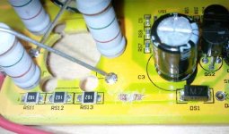
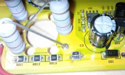
So I soldered the shunt down to ~650uOhms thinking that before I had soldered it to 750uOhms.
I also maxed out the battery and phase current in the software.
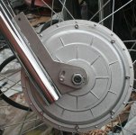
Well no matter what I did (44V, 88V, 9x7 hub, 10x6 hub) I just could not get the controller to draw more than 60A cont.
I lowered the software to 1/2 max and noted.... (drum roll please)..... 30A.
(imagine that

)
Well finally I went back and read my own post: It was ~250uA that I had soldered the shunt to :| :| :|
So... It makes sense that I cant go over 60A now.
I was able to hit 52mph on a 10x6 9C motor in a 26" wheel at 93V and 60A.
I was by no means topped out but I chickened out. All I have is a coaster brake and it is insanely sketchy to slow down from 50 like that

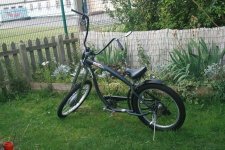
I have gone back to my Electra Cruiser for testing. As soon as I get my second controller built it will be 2wd
(No Doc, I dont have GPS, or Video, or Radar, or confirmation from NASA, or a notarized statement from a witness, or a time slip, or even a picture of the reading on my CA :wink: )
So... moral of the story appears to be that I need to open the controller (AGAIN) and solder that bad-boy down to 250uA.
Still does not jive with what doc claims....
He swapped the chip from the Crystalyte over to my kit.
Lets assume Kenny had programmed it to the maximum of 65A
Then Doc cut the resistance in half by adding 2 more shunts...
That is about a 650uOhm shunt and under those conditions I was only seeing peaks of 70A while Doc says he saw 170A
What was your final shunt value Doc? You must have done more than just add the 2 other shunts to make a total of 5.
You would have to have been well under 400uOhms to see those kinds of spikes.
-methods


