• Hello ES! We could use some help to get us past the finish line on building the new knowledgebase for the forum.
    Can you donate? Please see our fundraising page. Thank you!

Inverter Huawei I23002G1 / I23003G1 - Embedded Telecom Power (ETP) - 48V 42~58V 3000w

Hyperelectronic

🧲 New user
Joined
Sep 29, 2024
Messages
11
Location
Austria
Hello all of you,

Short introduction from my side, I am an electrical engineer / electronics developer / firmware programmer from Austria who likes to deal with all kind of electrical components / electronics / battery storage systems ranging from very small power levels (uCs) up to very large ones (EVs). I also over the years have gained a lot of experience in the field of reverse engineering.

Currently I am working on reverse engineering the "Embedded Telecom Power" (ETP) modules from Huawei to get them working standalone and I already managed to get the rectifier modules fully working (complete remote control, status communication, diagnostic data (including fan management) via can bus, etc.) and currently already use them to charge my powerwall with the excess power of my solar system (3x R4875G1 modules connected to 3 phase ac power and managed by a central ESP32 board with fully automated load management / power control). Additionally I also have the super high efficiency variant of this modules (R4850S1) for testing purposes.

I am now working specifically on the inverter type of modules but simply can not get them to work so far. I tried measuring and manipulating all possible data signals on the connector, but can not get it to communicate via can bus and therefore can not control it / enable the output.
I already found out, that this kind of module seems to do not have the auto addressing functionality that the rectifier modules have and therefore need static addressing (set via resistors, which I could not exactly determine because I do not have an original enclosure for it, but by a bit of trial and error found a combination where the module does not simply signal an slot error but still no communication is possible)
The main problem is, that there is zero communication comming from the module (as there is with the rectifier modules), also sending a lot of different messages to it made no difference, I even tried to brute force it, but with 29 bit of possible addresses and a nearly infinite amount of possible data combinations, there is really no big chance to get it working this way. I tried the northbound and southbound can bus at different states at the other pins, I am also 100% sure the whole communication chain is working properly, as if i plug a rectfier module into the same connector everything is working perfectly and with both types of modules only at the correct 125 kbit/s there is no immediate can bus error if I send messages to it.

The last thing I did is let the GPT do a deep resarch but that also did not result in anything useful. The only reference I got are some videos of a guy (on a chinese video platform) that seem to be a engineer at huawei and he has posted some short videos on the module working externally (from the comments it seems to be very likely that it was done with some special firmware on it).

I believe there must be some kind of unlocking sequence build into it (I am not sure if it is implemented in hardware via pins or software via can bus) or if it is only to protect people from mains output voltage or to lock us out from using it externally.
So the only way and hope I have, is you guys, as I am currently quite stuck.
Does anyone of you have an ETP23003 or ETP23006 enclosure and can reach out to me, so we can do a few measurements? (I think we will be able to get it working in a very short time)

I also have a lot more detailed informations / measurement values and images of the electronics of the modules that I could / will provide if needed, but as I am always very bussy, I do not have a lot of time for documenting it online in detail.

Thanks a lot to all of you in advance!
 
I don't have experience with these, but there is significant discussion about telecom PSU repurposing here. If you haven't already you might look at the other here (mostly in the battery technology section) to see if any of the stuff done on those applies to yours. This is perhaps the biggest:
 
I don't have experience with these, but there is significant discussion about telecom PSU repurposing here. If you haven't already you might look at the other here (mostly in the battery technology section) to see if any of the stuff done on those applies to yours. This is perhaps the biggest:
Thanks for your comment, i really appreciate it, this is quite a good thread as there are also a lot of pictures posted, but I already knew it (I have even read it multiple times already) and I believe also nearly everything I could find anywhere about it.
 
I would also be very interested in any information about getting this inverter working outside the enclosure. I have the I23003G1, and naively assumed it would just start pumping out CAN messages like R4850/4875. I haven't done any testing yet, other than power it on connected to CAN...

By slot error, do you mean all three LEDs lighting up? If so, what did you do to solve that? And do you get any AC output at this point?

I assumed the unit needed some kind of AC signal to sync to, and maybe that was the problem based on the presence of "Parallel signal" pins: I23003G1 Inverter Module User Manual V1.0 | PDF | Power Inverter | Power Supply
 
I originally had expected the same and before I bought it, I was quite sure, that it would behave exactly the same as the rectifier modules do, which unfortunately seems to be everything else than true.

Correct, if nothing is connected to address pins 1 or 2, all three leds are lit (the red led is signaling an slot detect / address error), even if the pskill pin is connected to dc- to signal a fully plugged-in module, but this connection at least half way starts the module (it's starting the conversion from input voltage to the dc bus voltage (internaly measured at around 396 VDC) (only pulsating because no power gets drawn and therefore no discharge of dc bus except the bleeder resistors) but no communication via can bus and also no output is present).
If you additionally connect address pin 1 to dc- and address pin 2 to an external supply of greater than 2.2 VDC (for my testing I keept at 2.8 VDC but tried ranges up to arround 25 VDC as I have found some loose informations on a chinese forum, that on the ETP48xxx enclosures the range for the reference circuit might go up to arround half the dc input (not sure if it is true, but there really should not be any harm to it, even if it is way to high, because the module is compliant with international emc standard (with which I am very familiar with) and therefore gets tested with such and even higher levels on any exposed pins at certification) and then supply the module with power the red fault indicator led stays off (only the yellow and green leds are on) but still no communication or output.

From what I have found out so far, I am also not expecting that any of the sync signals need to be present for a single module to work (this section is also separated on the user manual), but I also have already tried hooking up a lot of different signals onto the parallel signal pins, unfortunately with no luck or change in behaviour.

I am really wondering if there must be a special signal / communication present on the DIO+ and DIO- pins to unlock the module.
 
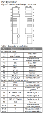
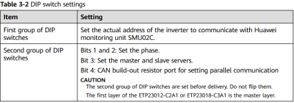
For everyone that is curious, some informations specified in the original user manuals of the module and enclosure:

1.) Pinout of the I23003G1 inverter module

2.) Description of the dip switches that set the levels of the address pins 1 and 2
I believe they are directly (with some simple ciruit) connected to the 2 individual address pins on the module (so first group address pin 1 and second group address pin 2) but can not verify it as I do not have an enclosure for it.
But from my understanding, it would make sense why it is indicating an error without a connection of the second address pin, because it would maybe think it is in slave mode and therefore needs the parallel signals, which are not present.
 

Attachments

  • 1748071062254.png
    1748071062254.png
    68 KB · Views: 13
  • 1748071249593.png
    1748071249593.png
    55.5 KB · Views: 12
I don't have experience with these, but there is significant discussion about telecom PSU repurposing here. If you haven't already you might look at the other here (mostly in the battery technology section) to see if any of the stuff done on those applies to yours. This is perhaps the biggest:
,here is the video of controller
 
Hello all of you,

Short introduction from my side, I am an electrical engineer / electronics developer / firmware programmer from Austria who likes to deal with all kind of electrical components / electronics / battery storage systems ranging from very small power levels (uCs) up to very large ones (EVs). I also over the years have gained a lot of experience in the field of reverse engineering.

Currently I am working on reverse engineering the "Embedded Telecom Power" (ETP) modules from Huawei to get them working standalone and I already managed to get the rectifier modules fully working (complete remote control, status communication, diagnostic data (including fan management) via can bus, etc.) and currently already use them to charge my powerwall with the excess power of my solar system (3x R4875G1 modules connected to 3 phase ac power and managed by a central ESP32 board with fully automated load management / power control). Additionally I also have the super high efficiency variant of this modules (R4850S1) for testing purposes.

I am now working specifically on the inverter type of modules but simply can not get them to work so far. I tried measuring and manipulating all possible data signals on the connector, but can not get it to communicate via can bus and therefore can not control it / enable the output.
I already found out, that this kind of module seems to do not have the auto addressing functionality that the rectifier modules have and therefore need static addressing (set via resistors, which I could not exactly determine because I do not have an original enclosure for it, but by a bit of trial and error found a combination where the module does not simply signal an slot error but still no communication is possible)
The main problem is, that there is zero communication comming from the module (as there is with the rectifier modules), also sending a lot of different messages to it made no difference, I even tried to brute force it, but with 29 bit of possible addresses and a nearly infinite amount of possible data combinations, there is really no big chance to get it working this way. I tried the northbound and southbound can bus at different states at the other pins, I am also 100% sure the whole communication chain is working properly, as if i plug a rectfier module into the same connector everything is working perfectly and with both types of modules only at the correct 125 kbit/s there is no immediate can bus error if I send messages to it.

The last thing I did is let the GPT do a deep resarch but that also did not result in anything useful. The only reference I got are some videos of a guy (on a chinese video platform) that seem to be a engineer at huawei and he has posted some short videos on the module working externally (from the comments it seems to be very likely that it was done with some special firmware on it).

I believe there must be some kind of unlocking sequence build into it (I am not sure if it is implemented in hardware via pins or software via can bus) or if it is only to protect people from mains output voltage or to lock us out from using it externally.
So the only way and hope I have, is you guys, as I am currently quite stuck.
Does anyone of you have an ETP23003 or ETP23006 enclosure and can reach out to me, so we can do a few measurements? (I think we will be able to get it working in a very short time)

I also have a lot more detailed informations / measurement values and images of the electronics of the modules that I could / will provide if needed, but as I am always very bussy, I do not have a lot of time for documenting it online in detail.

Thanks a lot to all of you in advance!

try this one
 
I would also be very interested in any information about getting this inverter working outside the enclosure. I have the I23003G1, and naively assumed it would just start pumping out CAN messages like R4850/4875. I haven't done any testing yet, other than power it on connected to CAN...

By slot error, do you mean all three LEDs lighting up? If so, what did you do to solve that? And do you get any AC output at this point?

I assumed the unit needed some kind of AC signal to sync to, and maybe that was the problem based on the presence of "Parallel signal" pins: I23003G1 Inverter Module User Manual V1.0 | PDF | Power Inverter | Power Supply
Hello interested people,

very good news for you, I managed to get the I23003G1 module finally working, also nearly finished the reverse engineering of the full can communication protocol for it.

1a.jpg

Next steps on my list are getting these modules working in parallel and furthermore, even in a 3-phase configuration (120° phase shift) to finally power my full home with them and maybe even do some phase sync and try to feed into the grid (I am not fully sure, if this is even possible with the default module firmware, as currently I found no fine adjustment for voltage and dynamic fine adjustment for frequency, just the "type" by enum values (but this gets executed very precisely, so there is definitely quite some high potential).

Currently I am very busy and also this project by now is also by far one of the most expensive reverse engineering projects I have ever done. Currently I have already bought equipment for nearly $1500 for it, so if anybody would really like to get some "crazy" projects like these going and could afford to support me with just some small amount, it would really help me a lot. As I am actually no "coffee person", everything would be directly spent on new equipment ;) My support link: https://ko-fi.com/hyperelectronic

For now, stay tuned, I will definitely post updates / a full guide after I finished documentation or maybe even record some videos, if time allows for it!
 
Ohh, nice work! This is definitely exciting as I had kind of given up on this inverter myself.

Even just getting it working in single-phase and with a few CAN "statistics" would be enough for me.

Looking forward to the guide!
 
Status update: Quite a lot of progress during the last months (even though i was quite busy with other stuff), by now got 3 modules and managed to build a working cluster with them so that I can continue testing and finish my protocol definition.

You can see a short video of the current state at:
⚡Huawei I23003G1 Inverter Module - Standalone Operation
(Unfortunately not ac phase synced yet)

I hope I have some spare time in the next weeks to do further testing and therefore can share more information with you, until then stay tuned ;)
 
Last edited:
Big update: Managed to get the parallel operation mode of these inverter modules fully working, so now even precise external control of the ac output voltage parameter is possible. Really turned out better than I would have hopped for! :giggle:

Short demo videos of the current state:
⚡Huawei I23003G1 Inverter Module - Dynamic Voltage Control
⚡Huawei I23003G1 Inverter Module - Dynamic Frequency Control

So by now, I am closer to finishing it all up than ever before. (Just have to sum up / document my latest discoveries, then it will finally be time to release all my findings.)

Thoughts for the future: I am also quite sure that grid feed operation can be done with this kind of modules (with the correct external grid monitoring / control circuitry), which would change quite a lot (I am speculating of maybe replacing the SUN 2000GTIL2 with them, this would be huge, way higher quality, higher output power, better control / monitoring (without quite heavy modifications), smaller form factor, hybrid operation, etc...) ! ;)
 
Crazy Update: Last step to convert my plans to reality were quite complex, needed to simultaneously generate 8 different PWM waveforms on the ESP32 (Master) while also communicating via 2 seperate CAN interfaces to control all 3 inverter modules in uniformity and now generate the beautifully looking 3 phases with a stable voltage / frequency and very accurate 120° of phase shift (all parameters fully controllable):

Huawei_I23003G1_3_Phase_Operation_1.jpg Oscilloscope Waveform Measurement:Huawei_I23003G1_3_Phase_Waveform.png

Further Notes: Also did some load testing, at first just with my air conditioner (inverter driven) and after that test succeeded, with my shop vac to check the behavoir with high inrush current spikes -> This modules handle it without any noticeable problems! (just a bit of voltage drop / some slight HF ripples can be seen)
In my last test, I even already managed to supply my whole home with backup power from this setup (including my induction stove), which also worked without any problems (even with quite high reactive loads)! :giggle:

(P.S. For everyone wondering, why I did my tests with 53Hz, I did this to prevent my normal PV inverters from syncing up with this setup and causing problems -> I first need to test, what happens, if other inverters (can) run in parallel with this modules, stay tuned! ;))
 
Huawei I23003G1 Reverse Engineering Documentation by ©Hyperelectronic:

Introduction to the topic:

First of all, the Huawei I23003G1 is a high-end, very lightweight, but very power-dense inverter module designed for supplying uninterruptible grid-independent, fully scalable / dynamically expandable backup power to server infrastructure / telecommunication equipment and is therefore used in all sorts of data centers and telecommunication facilities.
It is normally used in, for example, ETP (Embedded Telecom Power) enclosures but also can be found in quite a lot of other product line-ups from Huawei.
It is designed to supply up to 2.4 kW (real power) / 3 kVA apparent power while being fed from 48 V battery systems and features a fully digital, controllable output voltage and frequency while operating in single and also multi-inverter mode.
The module features full hot-swap support and gets cooled via a built-in fan and therefore can be run without any external cooling. For operation, an external controller featuring at least CAN communication and a very limited amount of passive components are needed.

Analysis of the enclosures:
The ETP23003-C1A1 is designed to house 2 pieces of rectifier / MIMO / iDCDU / MPPT (solar) modules and also one inverter-type module.
It can be supplied with mains voltage, directly charge batteries from it, or also from solar input while simultaneously supplying uninterruptible backup power with configurable output voltage / frequency and therefore can be used with all sorts of different batteries / chemistries as an uninterruptible AC power source.
It is from an operation standpoint / module wiring completely different from the ETP23006-C1A1 enclosure, even if both are able to run with the same type of inverter modules.
It uses a user-exchangeable SMU11B slot, which must be installed to get the inverter module to even start up without erroring out at power-up (the whole setup / control is done via the SMU).
The enclosure just statically connects the AC_D1 pin of the inverter module / slot to the negative battery input terminal (with a ferrite core filter in between) and the AC_D2 pin of the inverter module / slot to 3 of the 4 bits of the internally mounted dip switches / circuitry.
In the default configuration, this leads to 2.9 V on this signal pin while the enclosure is powered on.
Apart from these two pins, just the 2 CAN bus wires need to be connected to the SMU, this is everything that is needed for the inverter modules to operate in single module mode.
The enclosure itself is identified by a small internal I2C EEPROM that gets connected to the SMU via the internal connector / pin socket and exchanges the exact enclosure type, production information, and some configuration data (I recorded the communication / dumped the content of this EEPROM and was later able to also import it into an SMU02B that otherwise could not be connected physically to the same enclosure).

The ETP23006-C1A1 is designed to house 3 pieces of inverter modules (just inverter modules) and run them in parallel (at least 2 of them, one as a spare).
It gets powered directly from battery input and then converts it to a very potent single-phase output of 230 V 50 Hz with a maximum output power of 4.8 kW / 6 kVA, even if one module were to fail.
It operates the inverter modules without any external SMU / control device but can be connected to an external SMU via the RJ45 CAN connector for monitoring (I do not know if some parameter of the enclosure could even be changed, as my SMU11B does not feature the correct RJ45 CAN port and if connected to the internal CAN bus (from the connector / pin socket), it just sees the inverter modules by themselves (nothing else), which makes total sense, as the external RJ45 connector seems to be just directly connected to the northbound CAN bus of the inverter modules, so maybe the enclosure itself cannot be controlled at all / no change to the voltage / frequency can be made.
This enclosure itself is completely different from the ETP23003-C1A1. Here the pin AC_D1 is connected via an slot individual resistor to battery negative: 6.8 kOhm for slot 1, 20 kOhm for slot 2 and 61.7 kOhm for slot 3, this sets the base address of the inverter module, AC_D2 on the other hand, produces 2.87 V if the enclosure is powered (same as the previous enclosure), regardless if the module is connected or not.
In the enclosure itself, there is its own little MCU that is the master for the southbound CAN communication and also for generating the required sync signals.
All of the bits of the dip switches seem to be connected to this MCU itself and then get converted to a digital control message that is sent to the modules via the southbound CAN interface, so they do not change any physical pins on the modules for setting the address, phase, or other parameters.
The northbound CAN interface is connected to all 3 modules in parallel and then routed to the external RJ45 connector.
The Southbound CAN interface is connected via an isolator to the internal CAN transceiver and then to the internal MCU, which very likely has its internal CAN controller and is also paralleled on all 3 modules.
Apart from that, the 3 parallel signal pins are each connected in parallel on all 3 modules and then also routed to the internal MCU. They all must be connected to operate in parallel mode, as they provide the most relevant / very timing-sensitive sync parameters for operation.
The DIO+ / DIO- pins are not connected to anything in the enclosure, while the DIO pin is paralleled on all 3 slots (I did not find out if it is even used for something, it does not seem like it).

General facts about the module:
These inverter modules do have an internal precharge circuitry, so even if the module stays inserted in the slot connector and just battery power gets applied, there will be no sparks at all (this is different from the rectifier modules, which must be energized via external precharge circuitry first or by inserting them in an already powered slot (then the precharge pin can do it's job)).
The module by itself always powers up and therefore charges its bus capacitor (to arround 400 VDC), but if no correct CAN communication messages are present (in single operation) and no valid sync signals are present (in parallel operation), the output stage does not generate any output signal and also the internal output relay stays open.
If a communication master is present, the module can be commanded into sleep mode (low power consumption), where also the charging of the bus capacitor gets disabled, just communication stays active.
The output waveform of this inverter modules is a very clean sine wave with very low distortion and therefore suitable for all kinds of loads, while the internal switching frequency seems to lie at around 30 kHz.
The module base address can be set (regardless of the operation mode (single or parallel operation)) via the AC_D1 pin, you just need to connect a resistor (very rough values I tested before I had the original enclosure), 10 kOhm for address 1, 27.8 kOhm for address 2, 68 kOhm for address 3, and 120 kOhm for address 4 (yes, this also seems to work), but leaving this pin open does not work. Very important!: Only addresses 1 and 2 will allow the module to start up in single operation mode (just communicating always works), although 4 addresses work in parallel operation.
You can simply generate the required voltage for the AC_D2 pin (independent of operation mode) via a 1 kOhm / 6.8 kOhm resistor voltage divider if you are supplying your communication logic via 3.3 V, which will create the required ~ 2.9 V.
For single operation, you additionally just need the 2 pins for the northbound CAN interface, so these inverter modules can be interfaced via all available backplane connectors for the R4850G2 / R4875G1 modules!
For parallel operation, you need to be a bit creative (for interfacing these modules), as you also need the 3 parallel signal wires as well as the southbound CAN interface (see next paragraph) and also absolutely need to know what you are doing (otherwise you will risk quite costly damage) / need to be quite good at programming, as you will need to manage to create at least 3 different PWM signals (different duty cycle, phase and also frequency) per module, which additionally also need to be (at least part of it) synchronized / timed to very high-speed CAN communication messages for the southbound CAN interface (sub 10 ms message interval).
In parallel operation, the base address can be offset via a southbound CAN frame, and therefore a few dozen modules can be operated via a single controller (I did not check the exact number of possible modules, as it seems to be quite high).
The logic voltage of these modules seems to be around 3.1 V (maybe internally 3.3 V and externally just slightly lower because of the built-in isolation).
The AC_D1 and AC_D2 are the only control pins that are not isolated and therefore referenced to battery voltage.
All parallel signals seem to be fully isolated, while also both CAN interfaces seem to be isolated as well.
The module features a lot of control / monitoring options via the CAN interface, while in single module operation it seems like the output voltage and frequency can just be set in predefined ENUM-based values, while in parallel operation the frequency can be steplessly controlled via the external sync signals, while the output voltage can be adjusted in real-time via the southbound CAN communication and therefore a fully automated load balancing between modules is possible.
In parallel operation the absolute maximum range for the possible output voltage lies between 170 and 275 V and the output frequency between 40 and 70 Hz, but this large range might not be stable at all input voltages / load rates.
The frequency needs to be adjusted in a continuous fashion, as if a too-large step is created, the module will lose sync and temporarily disable its output.

Facts about the test environment:
I also bought a used SMU02B from eBay, but it is not able to see the inverter modules at all, as they seem to be implemented in a later firmware version, which I cannot get because I am not a Huawei business partner.
I also tried everything I could imagine, registering the product itself did not work, as it was part of a carrier contract.
Contacting the support itself was just a waste of time, as they did not give me anything, as they immediately tried to get my business contract ID / certification (which I do not have as a private person).
Also, contacting every meaningful seller on AliExpress and eBay did not get me anywhere, so let's say I had a lot of fun...
For parallel operation, I needed the backplane connector with the parallel signal / southbound CAN pins, which are not sold anywhere, so I built myself some by buying multiple ones of the R4875G1 type (screw terminal), as with one of these, you could disassemble them (get the pins out) and build yourself one fully equipped for parallel operation.
Attention: This is not possible with the type for the R4850G2 modules (cable lug / pluggable connector), as there are no slots for inserting the extra pins in the parallel positions.

Project Summary / Thoughts:
To get to this point, it took me around one and a half years of a lot of online research and communication with Chinese suppliers to get all the necessary equipment / enclosures and even more time building and reverse engineering this whole system.
Notice I had to do all of that in my already very limited free time.
This whole project by now has cost me over 3000 € in equipment, so I would really be happy for everyone that can afford to supply such crazy and absolutely insane / cost-intensive projects, as even they are quite a lot of work, they are not only a joy for me to work on, but also for all of you for getting even more crazy equipment to play with / use in DIY projects or even professional environments.

Link to relevant documents:

Link to the preliminary protocol documentation: (Just an early-stage draft I already did it at the end of last year, but it contains the most relevant data)
This documentation will get updated as soon as I have more time for it. (I already have a few findings that need to be further tested and documented, as well as the whole southbound CAN communication, which is missing by now.
This by the way, is a completely other topic and I focused on getting the general documentation ready first, as it already took way to long.)
In the meantime, you can leave your notes in the spreadsheet, I will be reviewing / checking them before inserting it into the documentation.

If anybody has some further questions about any of the tests I did / needs further help or just more details, this is just the tip of the iceberg, I have a lot of further data / analysis information / data logs, so feel free to leave your comment below! ;)

:) By the way, you can support me via: https://ko-fi.com/hyperelectronic :)
 
Hi @Hyperelectronic,

Thanks for the impressive work. I read it through attentively and understood almost nothing - my fault ;). My use case is to generate single phase 220 v 50 Hz pure sine AC from 48 v DC. Can you explain (using child-level language if possible) what hardware do I need on top of the battery and the inverter module, and the step-by-step instructions to achieving the goal.

If you sell this information pls provide a quote & terms.

I have a spare Raspberry PI to dedicate to the project if necessary.
 
Hello @Q8man you're welcome!

I now tried to simplify the whole description, so that just a minimum amount of parts / steps is required and everybody should be able to get this kind of modules working. :)

First of all, you need this kind of connector (if you don't want to solder directly to the pins of the module, which I would not recommend).
You can get these on AliExpress for example for quite cheap (Attention: Look for this exact type, not that one with the tab receptacle style ac connections that normally gets used with the R4850G2 / R4875G1):
1787516384589.png

Next, wire the connector (female type JST-socket) to the minimal circuit below (just these 3 resistors and a 3.3 V power supply are needed) and connect the CAN bus connector (male type JST-socket) to the CAN bus interface of your choice.
Connect CAN-L and CAN-H directly and enable the termination on the hat.
If you are using just a short cable, the termination resistor on the hat is sufficient, otherwise you also need one additional with 120 Ω near the inverter module:
1787515736555.png

If you are using a Raspberry Pi, for simplicity use a MCP2515 as CAN-controller (other types will work too but differ in setup).
In this case, you can also connect the 3.3 V (needed above) to the GPIOs of the Raspberry Pi (GND needs to be connected to DC- then):
1787513146996.png

Here you can find an explanation I wrote (for this exact type of CAN hat) and learn how to set everything up, that is really required to prepare the raw interface in Linux: CAN_HAT_Minimum_Setup_Guide.pdf

Furthermore I now also wrote a simple but very powerful Python script, with which you can monitor every value (I managed to reverse engineer / is relevant in any form) and you can also interactively control the inverter module with it (needed for enabling the output).
The whole functionality should be pretty much self explanatory:
Huawei_I23003G1_Device_Manager.JPG
It can be found here: Huawei_I23003G1_Device_Manager.py

I hope I can help you with that, so that you can get your project finally working.


(P.S. I do not sell these informations by the way (as the amount of time something like this takes, nobody would be prepared to pay anyway and I would do it anyways 😉), but if someone finds this really helpful, I would really enjoy, and give big shoutouts to everybody that shows his appreciation via the donation link above 😊)
 
Last edited:
Back
Top