I've built an Arduino battery cycle tester!

jonescg

100 MW
Joined
Aug 7, 2009
Messages
4,224
Location
Perth, Western Australia
Edited 24th June 2016 - new thread title might make it better for searching... I've built it and it works well. Code still being tweaked, but it's doing the job!

Hi all,

I often get new cells in for testing, and I have recently got in some LiCoO2 cells from First Energy Power which look pretty good for various applications, particularly e-bikes. I can do a capacity test pretty easily - I make a 2s2p pack, screw a couple of Anderson connectors into a ceramic terminal block and discharge it though a coil of steel wire in a bucket. My data logging consists of me with a voltmeter, current clamp and a stopwatch, and I write down the values as they tick over. I then plot them and get pretty cliff graphs.


Now, testing them at different C rates is great, and determining the useful capacity is important. But what's equally important is cycle life - how long can I do this kind of discharge-charge-discharge process for before the cells start to lose capacity/power.

I could just repeat my process, writing down a discharge curve every fifth run. After 25 or 30 cycles I'd have a fair idea of what they will be like in 300, 500 or 800 more.

But frock me that sounds mighty tedious! :lol: There has to be a way I can build an automated load tester which charges and discharges a standard voltage format day in day out. I have thought about a big SPDT switch which lets me toggle between charging and discharging, but I still have to be there to turn off the discharge and start the recharge.

So what options does the layman have for automating this process? I'm looking at up to about 50 amps max for a typical discharge of a 2s2p pack. The pack format is quite specific, as I want to replicate the termination system I use.

Any ideas and tips are most welcome!
 
Well, there are at least two dev threads going for such testers, both started in the last month or two (sorry I don't have a link). Maybe you can join in theirs and get them going sooner, and use it for yours?

Alternately, you could hack an RC charger to use a relay to your load or charger instead of whatever load or charger they use?
 
Thanks AW, I did try the search feature, but it's a bit of a needle in a haystack. I'm just kind of guessing what the search terms are.

I've drawn up a series of relays and contactors that can do the switching for me, but the data logging and automation is where I have no skills. Davec has sent me a few lines to follow, so I shall do that first.
 
I am not sure that all the ones I'm thinking of show up in it, but this search
http://www.endless-sphere.com/forums/search.php?keywords=test*&terms=all&author=&fid%5B%5D=14&sc=1&sf=titleonly&sk=t&sd=d&sr=topics&st=0&ch=300&t=0&submit=Search
of just the term

test*

in topic titles only, displayed by topic, just in the battery subforum, found these that might have at least some help:
http://www.endless-sphere.com/forums/viewtopic.php?f=14&t=66417&hilit=test%2A
http://www.endless-sphere.com/forums/viewtopic.php?f=14&t=56747&hilit=test%2A

and another that's a charger project but might be useful
http://www.endless-sphere.com/forums/viewtopic.php?f=14&t=42169&p=1029626#p1029626
The automation part I was thinking of would not be totally automated, but using an RC LiPo charger to do the controlling it could also do the logging if it has a USB port to a PC, and either works wiht Logview or simlar, or has it's own such program.

I guess for really high current you'd have to manually scale the data for that, if using an external shunt instead of the one inside the controller to do the logging with.

Or...you could use a set of Cycle Analysts with their serial outputs to log the info...if you can just use one instance of a terminal program to log all the serial-input data on one port, repeat for however many ports there are to monitor (separate computers if necessary?).
 
Cheers for the links - I've found plenty of testing done on cells, with some amazing logging too. But I guess what I want to do is automate the 50 amp load discharge and subsequent recharge, with data collection not even being the main goal - that can be every 5 cycles or so. I really just want to get some indication of cycle life at a given maximum continuous rate.

I work at Scitech as a presenter, and one of the workshop guys is big into electronics. He gave me an Arduino Uno and relay driver kit, which would be perfect for driving the charge and discharge contactors. It's programmable by USB and it will also spit out data if you have the right inputs. It will be a MASSIVE learning curve for me, but I think it's the only way to go.

I gather the analogue inputs are a 0-5 V signal, so a 2s2p pack would need a divider (where 8.4 V is turned into 5 V, and 6.8 V is 4.05 or something) then I can arrange it to discharge at 8.4 V, then when it's less than 6.8 V, stop the dishcarge and activate recharge. There needs to be a second true/false AND condition in there so that it doesn't oscillate at the bottom or top end.

I'll let you know how the learning process goes...
 
yeah i sent jonescg a pm- there are many ways to approach this task. I've done this type of work in the past while i was testing batteries - i used the light bulb discharger than switched to big resistors for discharging- but my methods were never automated as i was not doing repeated testing. i am not aware of any commercial products that do this kindof work either

MIT has developed a cell cycler for their a123 - but it looks like quiete a bit of work
http://mit-evt.blogspot.ca/2010/07/new-cell-cycler.html
http://praveens.mit.edu/~praveens/wp/wp-content/uploads/2010/06/CellCycler.pdf
https://www.youtube.com/watch?v=23kubKKcsiU

the Arduino Uno is a pretty good way to go-one needs to spend a bit of timing reading manuals but it will get the job done
Personally if i had to do this type of work- i would probably use an old PC and write software. i would design a discharger with a resistor and get a usb voltage meter that can read the shunt and the cell voltage -or perhaps interface the program with data coming in from the cellogs(which would be connected to shunt+cell)... i would also get a usb relay board controlled via my software that can manually turn / on/ off the discharger by software when needed... and another one to turn the charger/on off when its complete and than the discharger again
as for the charger again i would probably either bulk charger(MW power supply) or have single cell charger... i would have a usb voltage meter/ or cellogs going to the cell and once the voltage is at a certain state i would have the relay shut off via software than turn the discharger on

on that note- i know the hyperions can charge/ discharge cells as well and i believe the charging can be controlled via software.... so if one can get the API from them it might be possible to write software... i honestly would not trust the discharger on these products though....the product seems proprietary and not that accurate so this is probably not the way to go..

anyways good luck with it
 
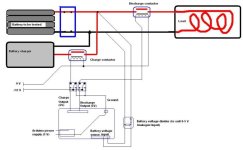
Right, so here is the basic circuit I'll be using to do the power testing:
cycle tester rig.JPG

And here is the program flow chart. It's fairly simple, and I don't even need a counter for however many cycles I want. Although, an abort input and a start input would probably be useful.

View attachment 1

The only thing left to do now is write some code to make it happen.
 
I just saw this tonight - in this instrucable he uses an inexpensive battery monitor with a buzzer and takes off the buzzer and uses those contacts to energize a latching relay to cut off discharge
http://www.instructables.com/id/Make-a-Battery-Protection-Circuit-low-voltage-cut-/
 
riba2233 said:
This is nice, but you cant do constant current. Your current will drop of as the voltage drops of.

I agree constant current is important for repeatable testing and particularly if you want to compare different cells against each other.

There are some pretty cheap widgets out there that you plug a resistive bank into and it then lets you select a specific discharge current but I haven't used one and can't quite tell if it will properly maintain that constant current throughout the discharge. 10A ones seem common but finding one that can control a 50A load may be more of a challenge.
eg FDY-10 on Aliexpress
FDY-10 user manual in PDF format
FDY-10 operation youtube clip
 
Not having a constant current is not the end of the world. A big bucket of water with a recirculating feature will ensure the load is consistent, even if it's not constant. I find taking the average current over the course of the discharge to be pretty good.

The latching relay idea is good - I entertained it for some time as I am an analogue kind of guy. However for the automation side of things, learning Arduino and code is probably better for me longer term.
 
Check out "Arduino Cookbook" by Margolis, likely available at your local library. I liked his clear descriptions and straightforward organization.

To help the flow diagramming I suggest this friendly, pithy introduction to state machines:

http://hacking.majenko.co.uk/finite-state-machine

Looks like fun.

Enjoy!
 
^^ Hey that blog is really cool! I'll definitely be following it in future.

But the good news is, after 15 months of procrastination I finally got around to designing and building a cell cycle tester!!! :mrgreen:

I'll add it in a few posts, as I've already covered in in the AEVA forum. But thanks to NeilG who wrote some clever code for me, the cell cycler is doing it's thing.

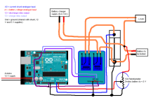
This is the basic circuit:
CelCyclerCircuitDiagram1.PNG

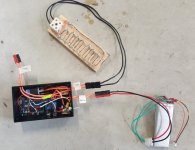
The analog inputs read the voltage of the battery being tested through a voltage divider, in this case a 10k pot. The pot is tuned so that the voltage of the battery when full charged is 4200 mV. Or whatever one cell would be. Of course you can use a single cell and not bother with the divider, but I want to be able to push some higher currents and more cells in series is the easiest way to do that.

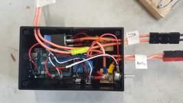
Cell Cycler Hardware.jpg

The load is about 5 or 6 strands of nichrome wire in parallel, following a maze and screw-terminated into a ceramic terminal block. I use 30 A Andersons throughout. The JST connector on the LiPo cells to be tested are handy for independent voltage monitoring of the battery as it charges and discharges.

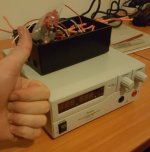
I charge it with a power supply capable of constant current. Best. Purchase. EVER>
New PS.jpg

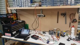
So when it's all set up it looks like this:
20160620_190332.jpg
 

Attachments

  • Cell Cycler.jpg
    Cell Cycler.jpg
    46 KB · Views: 4,400
I'll post the code here in a minute:

Code:
/* CellTester for Jonescg of AEVA Forums
 * Written by Neil Gibbs.
 * Anyone is free to use this code in any way they see fit.
 * There is no waranty bla bla bla etc on this code.
 * 
 * Description.
 * It uses a State Machine to keep track of the current phase in the cycle.
 * See comments for the State Machine below.
 * The constants defined below allow for:
 *    Calibrating the A2D convertor.
 *    Compensation for an external voltage divider.
 *    Set the number of cycles the tests will run for.
 *    Settting the Max voltage to terninate a charge cycle.
 *    Settting the Min voltage to terminate a discharge cycle.
 *    How often the sampling is performed.
 *    The time allowed between the phases of each cycle.
 *    A maximum time for either phase after which the process will stop.
 *    
 *  NOTES: If the current monitor is implemented it will only measure Charge
 *  current (A1 is +ve wrt ground). For safety sake place a 1-10k resistor in
 *  series with A1 incase there is a short somewhere during discharge. 
 *  This will prevent A2 from going too far -ve wrt ground and damage the 
 *  chip due to excessive input current.
 *  
 *  Depending on which display board is used A0 may be used for the keyboard.
 *  It might be wise to use A1 and A2 instead.
 *  I have used the AdaFruit display libraries and they work well so you 
 *  should have little trouble if you use their display boards.
 *  
 *  Debugging:
 *   Serial.print() statements send their output to the USB interface and this can
 *   be used with a terminal program such as Tera Term VT (I have tested this) 
 *   and it can also log to a file if needed.
 *   
 *   Please note that at the end of the test the cell(s) will be in a discharged state.
 */

// Define the hardware ports
#define DISCHARGE               13        // Discharge relay
#define RECHARGE                12        // Recharge relay
#define VOLTS                   A0        // Cell voltage
#define CURRENT                 A1        // CHARGE current (not discharge)

// Define the system constants
#define VCCVOLTS                4800L     // 5 volt rail actual value LEAVE 'L' SUFFIX as this needs to be a long int value
#define EXTERNDIV_NUM           2         // ratio for external voltage divider eg 2:1
#define EXTERNDIV_DENOM         1         // ratio for external voltage divider eg 2:1
#define NUMBEROFCYCLES          20        // Number of cycles to run
#define V_MIN                   6000      // Discharge min voltage (in mV)
#define V_MAX                   8400      // Charge max voltage (in mV)
#define SAMPLE_DELAY_MILLIS     1000      // Number of mS between voltage checks
#define RECOVERYTIME            10        // Number of Seconds between charge/discharge & discharge/charge  Max value is 32767
#define MAXSTATETIME            6000      // Number of Seconds allowed to be in each state (ie charging or discharging)  Max value is 32767
#define ON                      1         // Turn a relay On
#define OFF                     0         // Turn a relay Off


// State machine
#define STATE_START             0         // Setup for and start the charge cycle
#define STATE_CHARGING          1         // Monitor the charge cycle
#define STATE_DISWAIT           2         // Delay before and setup for discharging
#define STATE_DISCHARGING       3         // Monitor the discharging
#define STATE_CHGWAIT           4         // Delay before repeating the cycle
#define STATE_DONE              5         // All done

// Define the system variables
int           cellVolts;
int           chargeCurrent;
int           numberCycles;
int           currentState;
int           delayTimer;           
int           stateTimer;
unsigned long sampleDelay;
unsigned long cycleTime;


// readVoltage()
// Read the cell voltage and return the average of 4 readings.
// The result is scaled by the calibration value and also by the external divider.
// Return value is in milliVolts. ie 0 - 5000
int readVoltage()
{
 int temp = 0;

  for (int i = 0; i < 4; i++)
  {
    //Scale the A2D reading. The A2D returns 0 to 1023 for a voltage
    // range of 0 to the Arduino supply voltage (normally 5v).
    temp += (int)(((long)analogRead(VOLTS) * VCCVOLTS) / 1024); // Scale the A2D result
    delay(20);              // A short delay between readings
  }
  return (temp*EXTERNDIV_NUM)/(EXTERNDIV_DENOM*4);  // Compensate for the external voltage divider
}
  

// This function sets up the ports for use and initialises some variables.
void setup() {
  // Setup for debugging/logging
  Serial.begin(38400);
  Serial.println("setup()");    // Appends a CR - use Serial.print() for no CR

  numberCycles = 1;
  currentState = STATE_START;

  pinMode(DISCHARGE, OUTPUT);   // sets the discharge pin as an output
  digitalWrite(DISCHARGE, OFF); // Turn discharge relay off
  pinMode(RECHARGE, OUTPUT);    // sets the recharge pin as an output
  digitalWrite(RECHARGE, OFF);  // Turn recharge relay off

  cellVolts = readVoltage();    // Do first read to initialise the port

  // TODO - initialise your display
}


// This function is repeatedly called by the OS so we need to know where in the
// charge discharge cycle we are, so we use a State Machine.
void loop() 
{
  unsigned long now = millis();     // Get current timer value in mS

  if (now - sampleDelay > SAMPLE_DELAY_MILLIS)
  {
    sampleDelay = now;              // Reset the sampling base time

    switch (currentState)           // Go to the current state
    {
      case STATE_START:
        stateTimer = MAXSTATETIME;      // Setup state timeout value
        currentState = STATE_CHARGING;  // Next state is charging
        cycleTime = now;                // State start time
        digitalWrite(RECHARGE, ON);     // Turn charge relay on
        Serial.print("Cycle #");        // Logging
        Serial.println(numberCycles);
        
        // TODO update display
        break;
        
      case STATE_CHARGING:
        cellVolts = readVoltage();      // Do a read
        if (cellVolts > V_MAX)
        {
          // Voltage exceeds set threshold
          digitalWrite(RECHARGE, OFF);  // Turn charge relay off
          currentState = STATE_DISWAIT; // Next state is wait before discharge      
          delayTimer = RECOVERYTIME;    // Inter state delay time
          Serial.print("Charging Time: (mS) ");   // Logging
          Serial.println(now - cycleTime);
          
          // TODO update display
        }
        if (--stateTimer <= 0)
        {
          // Taken too long
          digitalWrite(RECHARGE, OFF);      // Turn relay off
          Serial.println("CHARGING TAKEN TOO LONG");  // Logging
          currentState = STATE_DONE;        // Next state is done
          
          // TODO update display
      }
        break;
      case STATE_DISWAIT:
        if (--delayTimer <= 0)
        {
          digitalWrite(DISCHARGE, ON);      // Turn discharge relay on
          currentState = STATE_DISCHARGING; // Next state is discharging
          stateTimer = MAXSTATETIME;        // Setup state timeout value
          cycleTime = now;                  // State start time
        }
        // TODO update display
        break;
        
      case STATE_DISCHARGING:
        cellVolts = readVoltage();          // Do a read
        if (cellVolts < V_MIN)
        {
          digitalWrite(DISCHARGE, OFF);     // Turn discharge relay off
          currentState = STATE_CHGWAIT;     // Next state is wait before charging
          delayTimer = RECOVERYTIME;        // Inter state delay time
          stateTimer = MAXSTATETIME;        // Setup state timeout value
          Serial.print("Discharging Time: (mS) ");  // Logging
          Serial.println(now - cycleTime);
        }
        if (--stateTimer <= 0)
        {
          digitalWrite(DISCHARGE, OFF);     // Turn discharge relay off
          Serial.println("DISCHARGING TAKEN TOO LONG");  // Logging
          currentState = STATE_DONE;        // Next state is done
        }
        
        // TODO update display
        break;

      case STATE_CHGWAIT:
        if (--delayTimer <= 0)
        {
          if (++numberCycles <= NUMBEROFCYCLES)
          {
            currentState = STATE_START;     // Next state is setup to charge
          }
          else
          {
             currentState = STATE_DONE;     // Next state is done
             digitalWrite(DISCHARGE, OFF);  // Turn discharge relay off
             digitalWrite(RECHARGE, OFF);   // Turn charge relay off
             Serial.println("Cycles finished"); // Logging
          }
        }
        
        // TODO update display
        break;

      case STATE_DONE:
        // TODO update display
        break;
    }
  }
}

Basically it's a finite state machine which uses Milis. I'm not 100% sure what these are, but I think its a convenient way of timing something. The 10 A relay actually drives a 15 amp automotive relay which I will soon upgrade to a 30 amp one. I use the 10 amp one for charging as it rarely goes above about 1 C charge anyway.

I have a 50 amp shunt in there as well. It's a 50 mV @ 50 A shunt, so the milivolts across it are roughly equal to amps. I did put my multimeter in series with the load to use my old-fashioned "stopwatch and notepad" method and it recorded about 7 amps, but this was a higher resistance than the load alone, so it's probably slightly higher.

A video of the robot switching from charge to discharge can be seen here (warning, there's an awkward pause while I wait for it to happen... :lol: )
[youtube]vsNd78qrlvY[/youtube]
 
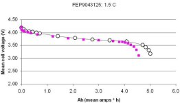
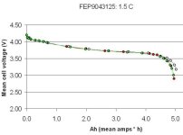
Now - the juicy bits: How does my FEP9043125 two-series battery stack up after being cycled 25 times?

Cell cycle discharge curve.jpg

The open circles are fairly early in the cell's life, while the pink squares are after about 25 cycles. This is a 1.5 C discharge, 1 C charge routine.

It looks bad, but remember I'm not charging it to 4.2 V per cell and letting it equilibrate for half an hours - I'm just putting it straight to discharge. So I will have to repeat the original test verbatim if I want to compare apples to oranges. Or, repeat this test in another 25 cycles time.

Still, it's SO MUCH EASIER to get a robot to do the job for me!
 
Finally added the code.

Remember that the code leaves the cells in a discharged state, and for some reason both the discharge and recharge relays are ON at the end of the last cycle. This is problematic, as a) it's not cool and b) it's trying to discharge at the same (or worse) rate as it's being charged. I'm going to have a play with it this afternoon to see if I can get it to end after a recharge, and make sure both relays are OFF.
 
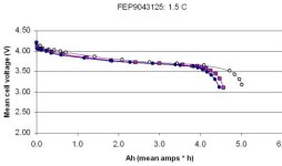
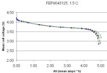
And after a total of 50 cycles (1 C charge, 1.5 C discharge):

Cell cycle discharge curve3.jpg

This could be a bit of cold weather sag as well as general decline, as its pretty cool in the shed right now - 9'C.

But, now that the cycler is working I can finally test cells under different circumstances and see what we get.

Any circumstances you're just dying to know what would happen?

Heavier loads? Compression? Cold weather? Presence of duct tape?

Temperature control will be tough, but I can try a few things easy enough.
 
Okay, so I have cycled this 2s battery 100 times and repeated the original balance charge and full discharge test I did back at the start. The graph above indicates there is significant capacity loss, but this seems mainly due to the lack of float charge (well, the slow charge process of balancing at 4.2 V).

So I have left these off the test profile, leaving only 1.5 C discharges after 3 cycles (open black circles) 75 cycles (red) and 100 cycles (green):

FEP9043125 after 100 cycles.jpg

The initial discharge test gave about 5.08 Ah, then after 75 cycles gave 4.96 Ah. After 100 cycles we've now got 4.94 Ah :) Pretty steady now it seems.

I'll post another discharge curve after 200 cycles...
 
I'm going to record an accurate discharge curve every 100 cycles now.

After 200 cycles of 1C charge and 1.5 C discharge, these FEP9043125 cells are still looking to be in pretty good shape:

FEP9043125 after 200 cycles.jpg

Down to about 4.87 Ah now from an initial 5.08 Ah. It's early days, but the extrapolation puts these cells at about 1000 cycles! And 1C is a fair old rate of charge, plus I think they often rate them based on a 1C discharge too.

Pretty happy with them!
 
You did very nice project! I am wondering why no comments from anybody. Sure this idea of testing cells is not new but contibuting and testing new type of cells is great!
In your code if you still do not have it i would add some rest time for cells after discharge. Cells basically do not handle well charging when still hot after discharge.
And i would love to see some higher C discharges :lol: Although this is probably cheap chinese cell it handled 200cycles pretty well :wink:
 
I never saw this thread before - awesome work Jonesy!
 
Well now I can finally test theories of what causes a cell to decline. Granted, 1000 cycles is about 2 months, 7 weeks if I increase the discharge rate.

Any cell by the way, not just pouch cells. My feeling has always been that the cycle life figures quoted for 18650s aren't as high as you'd like them to be, but then again, they're also a cell where pushing them past their continuous C rate is par for the course.

I'm very pleased with these particular cells as they have the best combination of C rate and energy density. FEP say they can make them 135 x 49 x 9 (L.W.T.) using the same special sauce and guarantee 10 C continuous (or 8 C as I learned).
 
Fast and easiest method: Im planning use cheap ebay capacity tester.
With arduino i can detect its output leds and charge (with 2$ DC-DC cc regulator)/discharge automatically. And use old android phone to take picture every min or so to dropbox.
Why many years no-one test cycle life of various cells here? Really interesting to know how long various cells last.
My cycle tests coming soon:
NCR18650B
18650PF
25R
GA
NC1
MJ1
US18650NC1
ICR18650-26J
LG 18650-B4
Samsung 18650-13L

electricbike 25r cycle test here stopped no reason :roll:
 
Last post on these cells I think -

I was away for a week with Voltron at Queensland Raceway, so the cells had a good week to relax. I balance charged up to 4.2 V per cell and did my usual discharge test after a total of 250 cycles:


Yes, the violet line represents the 1.5 C discharge curve after 250 cycles. And it's capacity appears to have increased :shock:

I will have to do another 10C discharge and see how hey stack up, but it looks like these cells are great for at least 1000 cycles, provided they don't spend too long at either end of their capabilities.

I think I've found Voltron's next battery :)
 
Back
Top