Working hard, I haven't had a chance to post.
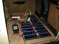
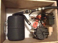
Above is the vacuum booster assembly for the brakes I completed a few nights back. It is mounted in the wood box that I got my 10ah cells from Andy/Falcon Ev during the 2007 Alt-Car-Expo, fresh off the boat from Taiwan. I think these are the same cells Justin at ebikes.ca is selling, they have served me well.
On the lower right is the actual pump and oil-filled muffler. The black cylinder on the left is the vacuum reservoir, on the hose is a check valve (left) and the vacuum sensor. Mounted to the left wall are the relays that monitor the sensor and turn on the vacuum pump.
I bought this kit from http://www.evsource.com/tls_braking_system.php for $366 delivered. Noise is reported to be a concern with these pumps, and this is touted as being quiet. I powered it up briefly and it did run quietly, though it sucked so much juice that it melted my test leads. I look forward to mounting this, I'll have to see how much juice it consumes, I may not have budgeted power adequately for it.
========================================
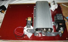
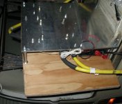
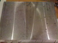
I bought the 20" x 14.75" x .375" aluminum sheet (seen below) on ebay for only $37 shipped. I also got a 16 "x 48" x 0.060" sheet of Phenolic plastic from the same vendor, both local to me so GREEN shipping.
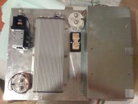
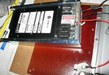
On the left is a Vicor Power supply. I bought this CHEAP when Doc Bass recommended them a ways back, but never used it - and now the mount that came with it is very handy! I am actually using a different vicor PSU than the one in the picture, but this is good for a test mount.
The Vicor's come with slots for (8) independant PSU that can be any combination of v/a, combined in series or parallel. I will fill (6) slots filled with 48v4.2a PSUs to charge the main pack. These can each be trimmed from 30v to 57v, giving me all sorts of combinations. For example:
I can parallel (4) of them to charge my 48v80ah pack at 16.8a, @0.2c.
I can do 3p2s to charge my future 96v80ah pack 12.6a.
I can do 2p3s to charge a potential 144v80ah pack at 8.4ah (@0.1c)
The remaining 2 slots I have filled with 12v 4.2a PSU that I will use to
a) charge the 12v pack that runs the brake booster, accessories, controller logic etc,
b) drive the EV200 contactor in the upper right, that closes the circuit on 48v-180v main-pack charger so that line is only active when the PSU is on.
c) open a relay that breaks the circuit on one of the motor-power contactors, so that if the charger is on, I can't power the motor.
Elegant, eh?
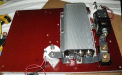
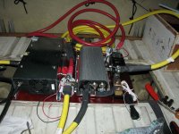
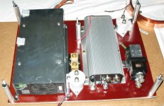
So the rest of the stuff... The Kelly KDH14500B controller is pretty obvious. On the left of it is the 500a/50ma shunt where I will land the 4/0 cable that supplies V+ from the battery. That will connect to the white EV200 Contactor in front of it via copper strap. This contactor's actuator leads will be hooked to an emergency cutoff switch up front. The 4/0 cable to S1 will connect to the other side of the contactor, as well as a copper strap that connects to the controller's B+ spade. The Controller's B- contactor will connect to the 600a kelly contactor on the left, which will be activated by the ignition.
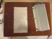
I figured a mix of contactors would be good, something that kills one might not damage the other. Although the aluminum plate is needed to cool the controller (and a handy sturdy mounting platform), all that exposed conductive metal was making me nervous, that's why I put down the phenolic plastic with a hole cut out for the controller.
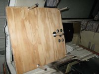
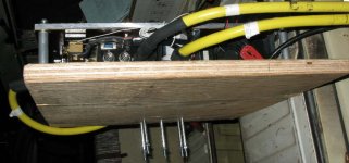
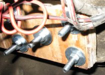
Oh, also note the 5 aluminum tubes/steel bolts in the corner and center. I am going to use them to mount a 1" plywood sheet to the assembly. This whole assembly will then flip over (wood side down) so that if it is ever accidentally exposed to water, it will drip down to the wood instead of pooling. I will also mount the throttle assembly/secondary return spring to this piece of wood, the subject of future photos.
Ah, the throttle. Friggen Fernando also CLIPPED my friggen throttle cable, so I don't have much to work with. Arg.
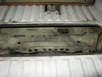
Anyhow, next I have to clean the engine bay, use the copper strip in the picture above to make laminated straps to connect the contactors/shunt/controller, make another laminated copper strap to connect S2/A2 on the motor... Then some wiring, and the whole mess goes into the bus with the brake vacuum pump and I should finally have reasonable control of it. Last bits will be to run an armoured casing with a bundle of wires to the front to connect my JUMBO CycleAnayst, and some control bits (emergency cutoff, brake sensor, etc) and the conversion will be complete - well, until I add more batteries that is.
Then I have to replace the burned wiring to the taillights etc and I can power up the bus's main 12v system for lights and signals. Then I have to repair a torn cv boot. Ah shoot, I forgot about the motor mount.
EDIT 12/14/12: replaced pictures lost when the forum crashed a few years ago.


